Table of Contents
Advertisement
Quick Links
Advertisement
Table of Contents

Related Manuals for Allied Telesis AT-WCU201G


Summary of Contents for Allied Telesis AT-WCU201G
-
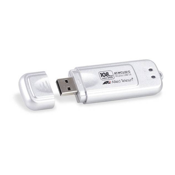
Page 1: Wireless Adapter
USB 2.0 Wireless Adapter AT-WCU201G Installation Guide 613-000260 Rev. A... - Page 2 Allied Telesyn, Inc. reserves the right to make changes in specifications and other information contained in this document without prior written notice. The information provided herein is subject to change without notice. In no event shall Allied Telesyn, Inc. be liable for any incidental, special, indirect, or consequential damages whatsoever, including but not limited to lost profits, arising out of or related to this manual or the information contained herein, even if Allied Telesyn, Inc.
-
Page 3: Regulatory Notes And Statements
AT-WCU201G Wireless Adapter Card Installation Guide Regulatory Notes and Statements Wireless LAN, Radio frequency electromagnetic energy is emitted from Wireless LAN Health and devices. However, the energy levels of these emissions are far less than the electromagnetic energy emissions from similar wireless devices such Authorization For as mobile phones. - Page 4 In France, the equipment must be restricted to the 2.4465-2.4835GHz (channels 10 -13) frequency range and must be restricted to indoor use. The following equipment: AT-WCU201G 54Mbps Wireless USB 2.0 Adapter. Is herewith confirmed to comply with the requirements set out in the Council Directive on the Approximation of the Laws of the Member States relating to the Electromagnetic Compatibility (89/336/EEC).
- Page 5 AT-WCU201G Wireless Adapter Card Installation Guide However, there is no guarantee that interference will not occur in a particular installation. If this equipment does cause harmful interference to radio or television reception, which can be determined by turning the equipment off and on, the user is encouraged to try and correct the interference by one or more of the following measures: ❑...
- Page 6 Regulatory Notes and Statements...
-
Page 7: Table Of Contents
Email and Telephone Support ............................12 Returning Products................................12 For Sales or Corporate Information ..........................12 Adapter Card Driver Updates ............................12 Chapter 1: Installing the AT-WCU201G Wireless Adapter Card ................... 13 Features ....................................14 LEDs ....................................15 Reviewing the Package Contents............................16 Installing the Adapter Driver ..............................17 Setting the Regulatory Domain............................ - Page 8 Contents...
-
Page 9: Preface
Preface This guide contains the installation instructions for the AT-WCU201G USB 2.0 wireless network adapter card. This preface contains the following sections: “Document Conventions” on page 10 “Where to Find Web-based Guides” on page 11 “Contacting Allied Telesyn” on page 12... -
Page 10: Document Conventions
Preface Document Conventions This guide uses the following conventions: Note Notes provide additional information. Caution Cautions inform you that performing or omitting a specific action may result in equipment damage or loss of data. Warning Warnings inform you that performing or omitting a specific action may result in bodily injury. -
Page 11: Where To Find Web-Based Guides
AT-WCU201G Wireless Adapter Card Installation Guide Where to Find Web-based Guides The installation and user guides for all Allied Telesyn products are available in Portable Document Format (PDF) from our web site at www.alliedtelesyn.com . You can view the documents on-line or... -
Page 12: Contacting Allied Telesyn
To obtain a RMA number, contact Allied Telesyn’s Technical Support at our web site: www.alliedtelesyn.com. For Sales or You can contact Allied Telesyn for sales or corporate information at our web site: www.alliedtelesyn.com. To find the contact information for your Corporate country, select Contact Us ->... -
Page 13: Chapter 1: Installing The At-Wcu201G Wireless Adapter Card
Chapter 1 Installing the AT-WCU201G Wireless Adapter Card This chapter contains the installation instructions for the AT-WCU201G wireless network adapter card. Sections in the chapter include: “Features” on page 14 “LEDs” on page 15 “Reviewing the Package Contents” on page 16 “Installing the Adapter Driver”... -
Page 14: Features
Chapter 1: Installing the AT-WCU201G Wireless Adapter Card Features USB 2.0 compliant interface IEEE 802.11b and 802.11g compliant 6, 9, 12, 18, 24, 36, 48, and 54 Mbps dynamic transmission rates for IEEE 802.1g 1, 2, 5.5, and 11 Mbps dynamic transmission rates for IEEE 802.1b Microsoft Windows 2000 and XP compatible 2.4 ~ 2.5 GHz frequency band... -
Page 15: Leds
AT-WCU201G Wireless Adapter Card Installation Guide LEDs The two LEDs on the AT-WCU201G adapter are defined in Table 1. Table 1. LED Descriptions State Description Link The adapter is receiving power. The adapter is not receiving power. The adapter has established a connection to a wireless router or access point. -
Page 16: Reviewing The Package Contents
Chapter 1: Installing the AT-WCU201G Wireless Adapter Card Reviewing the Package Contents The shipping package should contain the following items. If any item is missing or damaged, contact your Allied Telesyn sales representative for assistance: AT-WCU201G Wireless Adapter Software and Documentation CD... -
Page 17: Installing The Adapter Driver
If your computer launches the web browser when you insert the CD, minimize or close the web browser window. 3. Remove the cap from the AT-WCU201G wireless adapter, as shown in Figure 2. Figure 2. Removing the Cap from the AT-WCU201G Wireless Adapter 4. - Page 18 Chapter 1: Installing the AT-WCU201G Wireless Adapter Card 5. Connect the other end of the cable to the AT-WCU201G wireless adapter, as shown in Figure 3. Figure 3. Connecting the AT-WCU201G Wireless Adapter to the USB Cable Alternatively, you can connect the adapter directly to the USB port on the computer without the cable.
- Page 19 AT-WCU201G Wireless Adapter Card Installation Guide 6. In the Found New Hardware Wizard window, select No, not this time and click Next. The window shown in Figure 5 is displayed. Figure 5. Found New Hardware Wizard Window (2 of 3) 7.
- Page 20 Chapter 1: Installing the AT-WCU201G Wireless Adapter Card 8. Click Finish. This completes the procedure for installing the adapter driver on a Microsoft Windows system. Go to the next procedure, “Setting the Regulatory Domain” on page 21.
-
Page 21: Setting The Regulatory Domain
AT-WCU201G Wireless Adapter Card Installation Guide Setting the Regulatory Domain Caution The selection of your country or regulatory domain is critical to the proper operation of the wireless adapter and its adherence to the laws and regulations that govern the operation of wireless networks in your country. - Page 22 Chapter 1: Installing the AT-WCU201G Wireless Adapter Card 3. Click the Hardware tab. The Hardware tab is shown in Figure 8. Figure 8. System Properties Window - Hardware Tab (Microsoft Windows 4. Click Device Manager.
- Page 23 Figure 10. Expanded Network Adapters Selection If the Network Adapters selection does not include your new adapter, be sure that the adapter is securely connected to the USB port on the computer. 6. Double-click Allied Telesyn AT-WCU201g Wireless USB Adapter.
- Page 24 Chapter 1: Installing the AT-WCU201G Wireless Adapter Card The Properties window for the adapter is shown in Figure 11. Figure 11. AT-WCU201G Wireless Adapter Properties Window 7. Select the Advanced tab. The Advanced tab is shown in Figure 12. Figure 12. Properties Window - Advanced Tab...
- Page 25 AT-WCU201G Wireless Adapter Card Installation Guide 8. Click Country Region and select your country or regulatory domain from the Value pull-down menu 9. Click OK. This completes the procedure for installing the wireless adapter’s driver on your computer.
-
Page 26: Verifying The Driver Installation
Chapter 1: Installing the AT-WCU201G Wireless Adapter Card Verifying the Driver Installation To verify that the driver was correctly incorporated into the Microsoft Windows operating system, perform the following procedure: 1. Open the Control Panel. 2. Double-click on System. The System Properties window with the General tab is shown in Figure 7 on page 21. -
Page 27: Removing The Adapter Driver
AT-WCU201G Wireless Adapter Card Installation Guide Removing the Adapter Driver To remove the driver from the computer, perform the following procedure: 1. Connect the AT-WCU201G wireless adapter to the computer. For instructions, refer to Step 3 in “Installing the Adapter Driver” on page 17. - Page 28 Chapter 1: Installing the AT-WCU201G Wireless Adapter Card 8. Click OK. 9. Disconnect the wireless adapter from the computer. This completes the procedure for removing the adapter driver from the computer.
-
Page 29: Chapter 2: Using The Adapter's Configuration Utility
Chapter 2 Using the Adapter’s Configuration Utility This chapter describes the Wireless Configuration utility that comes on the CD included with your adapter. You can use the utility to configure the parameter settings on the adapter, such as its IP address and security settings. -
Page 30: Installing The Configuration Utility
Your system should automatically launch the CD and display the main window, shown in Figure 14. If this window does not appear, double- click on the My Computer icon, then double-click on the Allied Telesyn Installation CD icon. Figure 14. Software and Documentation CD Main Window 3. - Page 31 AT-WCU201G Wireless Adapter Card Installation Guide The prompt in Figure 15 is displayed. Figure 15. Internet Explorer - Active Content Warning Prompt 4. Click Run. The prompt in Figure 16 is displayed. Figure 16. File Download - Security Warning Prompt 5.
- Page 32 Chapter 2: Using the Adapter’s Configuration Utility 6. Click Run. The Welcome window of the InstallShield Wizard is shown in Figure Figure 18. InstallShield Wizard — Welcome Window 7. Click Next. The Choose Destination Location window of the InstallShield Wizard is shown in Figure 19.
- Page 33 Figure 20. InstallShield Wizard — Select Program Folder 9. Select the location where you want InstallShield to store an icon for the configuration utility and click Next. The default is the Allied Telesyn folder. (InstallShield Wizard creates the folder if it does not already exist.)
- Page 34 Chapter 2: Using the Adapter’s Configuration Utility 10. Select your country or regulatory domain from the pull-down menu and click OK. Caution The selection of your country or regulatory domain is critical to the proper operation of the wireless adapter and its adherence to the laws and regulations that govern the operation of wireless networks in your country.
-
Page 35: Starting The Configuration Utility
Windows toolbar. Figure 23. Configuration Utility Icon Alternatively, select the following from the Start Menu: Start -> Programs -> Allied Telesyn -> AT-WCU201G Configuration Wizard. The program consists of four tabs: Configuration, Status, Option, and About. - Page 36 Chapter 2: Using the Adapter’s Configuration Utility The section is useful in reviewing the networks that are currently available for you to connect to with the adapter, as well as viewing basic information about the networks. This information includes the following: ESSID - The name of the network.
- Page 37 AT-WCU201G Wireless Adapter Card Installation Guide In order for the wireless adapter to access one of the networks listed in Available WANs, you have to configure it with the network’s name and the appropriate security information. This is referred to as creating a Preferred WLAN profile.
-
Page 38: Creating A Preferred Wlan Profile
WEP security WPA-PSK and WPA2-PSK security Note The AT-WCU201G wireless adapter also supports Ad Hoc, WPA/ WPA2 Enterprise, and 802.1x authentication, but these topics are beyond the scope of this manual. To create a Preferred WLAN, perform the following procedure: 1. - Page 39 AT-WCU201G Wireless Adapter Card Installation Guide The Wireless Network Properties window is shown in Figure 26. Figure 26. Wireless Network Properties Window Depending on how you opened the window, some of the information may already be filled in for you.
-
Page 40: No Security
Chapter 2: Using the Adapter’s Configuration Utility No Security A Preferred WLAN without security is appropriate in a wireless network environment where there is no encryption or authentication between the wireless nodes and the wireless routers or access points. Caution A wireless network without security is vulnerable to unauthorized access. - Page 41 AT-WCU201G Wireless Adapter Card Installation Guide In a Shared Key environment a node must authenticate itself to the access point using a shared WEP key that is present on both the node and the access point. Only after a node is successful authenticated will the access point allow it access to the network.
-
Page 42: Wpa/Wpa2-Psk Security
Chapter 2: Using the Adapter’s Configuration Utility The key lengths for an ASCII key are as follows: – A key length of 64 bits requires 5 ASCII characters. – A key length of 128 bits requires 13 ASCII characters. – A key length of 152 bits requires 16 ASCII characters. - Page 43 AT-WCU201G Wireless Adapter Card Installation Guide 3. Click Data Encryption and select either TKIP (Temporal Key Integrity Protocol) or AES (Advanced Encryption Standard) from the pull-down menu. The encryption method must be the same on both the wireless node and the wireless access point.
- Page 44 Chapter 2: Using the Adapter’s Configuration Utility 7. Click OK to close the Wireless Network Properties window. The Preferred WLANs section of the Configuration tab should now include a new Preferred WLAN profile for a wireless network using WPA-PSK or WPA2-PSK security. 8.
-
Page 45: Configuring The Ip Address
AT-WCU201G Wireless Adapter Card Installation Guide Configuring the IP Address To configure the IP address for a Preferred WLAN profile or to activate the DHCP client, perform the following procedure: 1. Start the configuration program by clicking the program’s icon, shown in Figure 23 on page 35, located in the toolbar on the desktop. - Page 46 Chapter 2: Using the Adapter’s Configuration Utility The LAN Settings window is shown in Figure 28. Figure 28. LAN Settings Window 7. If you want the adapter to obtain its IP address, subnet mask, and default gateway from a DHCP server on your network, click Obtain an IP address automatically.
- Page 47 AT-WCU201G Wireless Adapter Card Installation Guide DNS server addresses and enter the IP address in the field. You can enter up to two IP addresses of domain name servers. The alternate DNS server address is used only if the server specified as the preferred DNS server does not respond.
-
Page 48: Deleting A Preferred Wlan Profile
Chapter 2: Using the Adapter’s Configuration Utility Deleting a Preferred WLAN Profile To delete a Preferred WLAN profile, perform the following procedure: 1. Start the configuration program by clicking the program’s icon, shown in Figure 23 on page 35, located in the toolbar on the desktop. The main window of the configuration utility is shown in Figure 24 on page 35. -
Page 49: Importing And Exporting Preferred Wlan Profiles
You can export a Preferred WLAN profile into a separate file and then import the file onto another computer. This can simplify the task of configuring a large number of AT-WCU201G adapters that are to have similar or identical Preferred WLAN profiles. -
Page 50: Importing A Preferred Wlan Profile
This completes the procedure for exporting a Preferred WLAN profile. By saving the profile onto a floppy disk or CD, you can transfer the disk to another computer that has an AT-WCU201G adapter and the configuration utility, and import the profile onto that system, as explained in the next procedure. - Page 51 AT-WCU201G Wireless Adapter Card Installation Guide The profile is incorporated as a Preferred WLAN into the configuration utility. The wireless adapter will establish a connection if it is within range of a wireless router or access point of the network defined by the...
-
Page 52: Working With Profile Groups
Chapter 2: Using the Adapter’s Configuration Utility Working with Profile Groups Profile groups allow you to organize your Preferred WLAN profiles. You can place the profiles in different groups to make them easier to find and manage. Creating profile groups is optional. There can be only one active profile group at a time. -
Page 53: Moving A Preferred Wlan Profile
AT-WCU201G Wireless Adapter Card Installation Guide 5. You can now add profiles to the new group by either creating them or, if they already exist, moving them from an existing group to the new group. For directions, refer to “Creating a Preferred WLAN Profile” on page 38 and “Moving a Preferred WLAN Profile”... -
Page 54: Deleting A Group
Chapter 2: Using the Adapter’s Configuration Utility 3. Click Rename. The Group Rename window is shown in Figure 33. Figure 33. Group Rename Window 4. Enter the new name for the group and click OK. The name can be up to 15 alphanumeric characters. -
Page 55: Selecting The Active Profile Group
AT-WCU201G Wireless Adapter Card Installation Guide Selecting the This procedure selects the active profile group for an adapter. The switch uses the profiles in the active group to establish a connection to a wireless Active Profile network. There can be only one active group at a time for a wireless Group adapter. - Page 56 Chapter 2: Using the Adapter’s Configuration Utility...
-
Page 57: Chapter 3: Microsoft Windows Xp
Chapter 3 Microsoft Windows XP This chapter contains the procedures for configuring the wireless adapter on a Microsoft Windows XP system. Sections in the chapter include: “Setting the IP Address” on page 58 “Quick Configuration” on page 62 “Manually Configuring the Wireless Adapter” on page 65 Note The wireless adapter is supported on Microsoft Windows 2000, but this guide does not contain instructions for configuring the adapter... -
Page 58: Setting The Ip Address
Chapter 3: Microsoft Windows XP Setting the IP Address To set the IP address of the adapter or to activate the DHCP client, perform the following procedure: 1. Open the Control Panel. 2. Double-click on Network Connections. An example of the Network Connections window is shown in Figure Figure 34. - Page 59 AT-WCU201G Wireless Adapter Card Installation Guide The Wireless Network Connections Properties window is shown in Figure 36. Figure 36. Wireless Network Connection Properties Window 4. Select Internet Protocol (TCP/IP), then click Properties.
- Page 60 Chapter 3: Microsoft Windows XP The Internet Protocol (TCP/IP) Properties window is shown in Figure Figure 37. Internet Protocol (TCP/IP) Properties Window 5. If you want the adapter to obtain its IP address, subnet mask, and default gateway from a DHCP server on your network, select Obtain an IP address automatically.
- Page 61 AT-WCU201G Wireless Adapter Card Installation Guide You are now ready to configure the adapter’s security system using the Wireless Adapter Configuration program.
-
Page 62: Quick Configuration
Chapter 3: Microsoft Windows XP Quick Configuration This procedure explains how to quickly configure the wireless adapter using Microsoft Windows XP. Note the following before performing this procedure: You must be within reception range of a wireless router or access point of the network. - Page 63 AT-WCU201G Wireless Adapter Card Installation Guide Windows displays the SSIDs of the detected wireless networks in the Wireless Network Connection window. An example of the window is shown in Figure 39. Figure 39. Wireless Network Connection Window 3. Double-click on the wireless network to connect to or, alternatively, click once on the network and click Connect.
- Page 64 Chapter 3: Microsoft Windows XP If there is no security on the wireless network, the Wireless Network Connections window in Figure 41 is displayed. Figure 41. Wireless Network Connection - No Security 4. Click Connect Anyway. At this point, the wireless adapter establishes a connection with the wireless router or access point.
-
Page 65: Manually Configuring The Wireless Adapter
WEP security WPA-PSK and WPA2-PSK security Note The AT-WCU201G wireless adapter also supports Ad Hoc, WPA/ WPA2 (Enterprise), and 802.1x authentication, but these topics are beyond the scope of this manual. To manually configure the wireless adapter’s security settings, perform the following procedure: 1. - Page 66 Chapter 3: Microsoft Windows XP The Wireless tab is shown in Figure 42. Figure 42. Wireless Tab 6. Click Add. The Wireless Network Properties window is shown in Figure 43. Figure 43. Wireless Network Properties Window...
-
Page 67: No Security
AT-WCU201G Wireless Adapter Card Installation Guide 7. Go to the appropriate subsection below for instructions on how to configure the Wireless Network Properties window for your wireless security system: “No Security” on page 67 “WEP Security” on page 67 “WPA/WPA2-PSK Security” on page 68... -
Page 68: Wpa/Wpa2-Psk Security
Chapter 3: Microsoft Windows XP 6. Click Key Index and specify the position of the encryption key in the encryption key table on the wireless router or access point. The range is 1 to 4. 7. Click OK. WPA/WPA2- To configure the Wireless Network Properties window for WPA-PSK or WPA2-PSK security, do the following: PSK Security 1. -
Page 69: Appendix A: Technical Specifications
Appendix A Technical Specifications This appendix lists the technical specifications of the AT-WCU201G wireless adapter. General Compliance Standard IEEE 802.11, IEEE 802.11b, IEEE 802.11g Bus Interface Universal Serial Bus (USB) 2.0 Antenna Type Integrated antenna IEEE 802.11b Operation Standard IEEE 802.1b... - Page 70 Appendix A: Technical Specifications Channel Numbers 11 channels for United States 13 channels for European countries Data Rates 6, 9, 12, 18, 24, 36, 48, 54 Mbps Media Access Protocol CSMA/CA with ACK Transmitter Output Typical RF output power at each data rate Power +15 dBm at 48 and 54 Mbps +16 dBm at 36 Mbps...
-
Page 71: Appendix B: Regulatory Domains
Appendix B Regulatory Domains This appendix lists the IEEE 802.11g channels supported by the world’s regulatory domains. Regulatory Domains Channel Frequency Germany, United Identifier (MHz) Italy, United States Mexico France Kingdom (FCC) (ETSI) 2412 2417 2422 2427 2432 2437 2442 2447 2452 2457... - Page 72 Appendix B: Regulatory Domains...
Need help?
Do you have a question about the AT-WCU201G and is the answer not in the manual?
Questions and answers