Table of Contents
Advertisement
Quick Links
Owner's Operator and Maintenance Manual
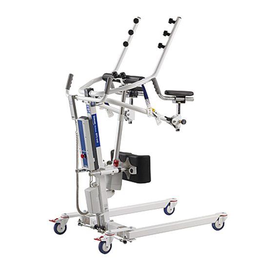
Reliant™ 440
Patient Lift
DEALER: This manual MUST be given to
the user of the patient lift.
USER: BEFORE using this patient lift, read
this manual and save for future reference.
For more information regarding
Invacare products, parts, and services,
please visit www.invacare.com
Advertisement
Table of Contents

Related Manuals for Invacare Reliant 440


Summary of Contents for Invacare Reliant 440
- Page 1 Patient Lift DEALER: This manual MUST be given to the user of the patient lift. USER: BEFORE using this patient lift, read this manual and save for future reference. For more information regarding Invacare products, parts, and services, please visit www.invacare.com...
-
Page 2: Symbol Legend
ACCESSORIES WARNING Invacare products are specifically designed and manufactured for use in conjunction with Invacare accessories. Accessories designed by other manufacturers have not been tested by Invacare and are not recommended for use with Invacare products. SYMBOL LEGEND "ATTENTION, see instructions for use". -
Page 3: Table Of Contents
TABLE OF CONTENTS SYMBOL LEGEND ... 2 SPECIAL NOTES ... 5 LABEL LOCATION ... 6 TYPICAL PRODUCT PARAMETERS ... 7 Reliant 440 Patient Lift ...7 SECTION 1—GENERAL GUIDELINES ... 8 Weight Limitation...8 Assembling the Lift ...8 Using the Sling ...8 Operating the Lift ...9... - Page 4 Care and Maintenance of Stand-Up Lift ...32 Detecting Wear and Damage ...32 Cleaning the Sling and the Lift ...32 Replacing Electric Actuator...33 Maintaining the Base Adjustment...34 Replacing the Casters ...35 Front Caster...35 Rear Caster ...35 LIMITED WARRANTY ... 36 Reliant™ 440 Part No 1141431...
-
Page 5: Special Notes
Warning indicates a potentially hazardous situation which, if not avoided, could result in death or serious injury. Caution indicates a potentially hazardous situation which, if not avoided, may result in property damage or minor injury or both. NOTICE Reliant™ 440... -
Page 6: Label Location
LABEL LOCATION LABEL LOCATION Reliant™ 440 Part No 1141431... -
Page 7: Typical Product Parameters
TYPICAL PRODUCT PARAMETERS Reliant 440 Patient Lift Height at Sling Hook-up - MAX.: Height at Sling Hook-up - MIN.: Base Width OPEN: Base Width CLOSED: Base Height (Clearance): Base Length: Caster Size (FRONT/REAR): Weight Capacity: Weight Out of Carton: Battery:... -
Page 8: Section 1-General Guidelines
Check all parts for shipping damage before using. In case of damage, DO NOT use the equipment. Contact the Dealer for further instructions. The Invacare patient lift is NOT a transport device. It is intended to transfer an individual from one resting surface to another (such as a bed to a wheelchair). Moving a person suspended in a sling over ANY distance is NOT recommended. DO NOT attempt any transfer without approval of the patient’s physician, nurse or medical assistant. Thoroughly read the instructions in this Owner’s Manual, observe a trained team of experts perform the lifting procedures and then perform the entire lift procedure several times with proper supervision and a capable individual acting as a patient. Invacare Stand Assist and Transfer slings are specifically designed to be used in conjunction with Invacare patient lifts. Slings and accessories designed by other manufacturers are not to be utilized as a component of Invacare’s patient lift system. Use of these products is prohibited and will void the lift’s warranty. Use the sling that is recommended by the individual’s doctor, nurse or medical assistant for the comfort and safety of the individual that is being lifted. Weight Limitation DO NOT exceed maximum weight limitation of the patient lift. The weight limitation for the Reliant 440 Patient Lift is 440 lbs. Assembling the Lift DO NOT overtighten mounting hardware. This will damage mounting brackets. Using the Sling Individuals that use the Stand Assist Sling MUST be able to support the majority of their own weight, otherwise injury may occur. Stand Assist Slings: DO NOT use the stand assist sling in combination with the patient lift as a transport device. It is intended to transfer an individual from one resting surface to another (such as a bed to a wheelchair). Moving a person using the stand assist sling in combination with the patient lift over ANY distance is NOT recommended. Reliant™ 440 Part No 1141431... -
Page 9: Operating The Lift
Transfer Slings: Before lifting the patient, make sure the bottom edge of the transfer sling is at the base of the spine and the patient’s arms are outside the transfer sling. Transfer Slings: DO NOT raise the patient to a full standing position while using the transfer sling, otherwise injury may occur. DO NOT use any kind of plastic back incontinence pad or seating cushion between patient and sling material that may cause the patient to slide out of the sling during transfer. After each laundering (in accordance with instructions on the sling), inspect sling(s) for wear, tears, and loose stitching. Bleached, torn, cut, frayed, or broken slings are unsafe and could result in injury. Discard immediately. DO NOT alter slings. Be sure to check the sling attachments each time the sling is removed and replaced, to ensure that it is properly attached before the patient is removed from a stationary object (bed, chair or commode). If the patient is in a wheelchair, secure the wheel locks in place to prevent the chair from moving forwards or backwards. When connecting slings equipped with color coded straps to the patient lift, the shortest of the straps MUST be at the back of patient for support. Using long section will leave little or no support for patientʹs back. The loops of the sling are color coded and can be used to place patient in various positions. The colors make it easy to connect both sides of the sling equally. Make sure that there is sufficient head support when lifting a patient. Operating the Lift Make sure there is an audible click when mounting battery on the battery charger to confirm proper mounting. Otherwise, injury or damage may occur. Use the handles to push or pull the patient lift. Lifting the Patient Before positioning the legs of the stand up lift around the patient, make sure that the patient’s feet are out of the way of the foot plate, otherwise injury may occur. Adjustments for safety and comfort should be made before moving the patient. Patientʹs arms should be outside of the sling straps. Part No 1141431 Reliant™ 440... -
Page 10: Transferring The Patient
SECTION 1—GENERAL GUIDELINES Before lifting a patient from a stationary object (wheelchair, commode or bed), slightly raise the patient off the stationary object and check that all sling attachments are secure. If any attachment is not correct, lower the patient and correct the problem, then raise the patient and check again. During transfer, with the patient suspended in a sling attached to the lift, DO NOT roll caster base over objects such as carpet, raised carpet bindings, door frames, or any uneven surfaces or obstacles that would create an imbalance of the patient lift and could cause the patient lift to tip over. Use steering handle on the mast at ALL times to push or pull the patient lift. Invacare recommends locking the rear swivel casters ONLY when positioning or removing the sling (stand assist or transfer) from around the patient. Invacare does NOT recommend locking of the rear casters of the patient lift when lifting an individual. Doing so could cause the lift to tip and endanger the patient and assistants. Invacare DOES recommend that the rear casters be left unlocked during lifting procedures to allow the patient lift to stabilize itself when the patient is initially lifted from a chair, bed or any stationary object. Transferring the Patient Before transferring, check that the product’s weight capacity can withstand the patientʹs weight. Wheelchair wheel locks MUST be in a locked position before lowering the patient into the wheelchair for transport. Performing Maintenance Regular maintenance of patient lifts and accessories is necessary to assure proper operation. After the first 12 months of operation, inspect all pivot points and fasteners for wear. If the metal is worn, the parts MUST be replaced. Perform this inspection every six months thereafter. DO NOT overtighten mounting hardware. This will damage mounting brackets. Casters and axle bolts require inspections every six months to check for tightness and wear. Reliant™ 440 Part No 1141431... -
Page 11: Section 2-Assembly
NOTE: For this procedure, refer to FIGURE 2.1 on page 12. NOTE: The Reliant 440 is packed partially assembled for shipping purposes. 1. Remove all contents from the box and place the unit on a workbench or table. 2. Remove the two mounting screws, washers, and locknuts connecting the mast to the base (Detail “A”). 3. Remove the mast from the base. 4. Position and re‐attach the mast to the base using the two mounting screws, washers, and locknuts removed in STEP 2 (Detail “B”). Securely tighten. 5. Insert the pins of the rod ends up through the tabs on the base (Detail “B”). 6. Attach the pins of the rod ends to the tabs using the two locknuts and washers. Securely tighten. 7. Cut the cable tie securing the actuator (Detail “C”). 8. Swing the actuator forward so that it is out of the way. 9. Swing the boom up and over to the front. 10. Attach the push handle to the back of the mast using the two mounting screws, locknuts, and washers which are provided (Detail “D”). 11. Attach the kneepad. Refer to Attaching the Kneepad on page 13. Part No 1141431 WARNING Reliant™ 440... - Page 12 DETAIL “A” Mast Mounting Screws Base DETAIL “C” Cable Tie Boom FIGURE 2.1 Assembling the Patient Lift Reliant™ 440 Mast Ends Mounting Screws Actuator Mast Push Handle DETAIL “B” Mounting Locknut Screws Washer Base Washer Locknut DETAIL “D” Washers Locknuts...
-
Page 13: Attaching The Kneepad
1. Connect the top of the actuator to the boom using the bolt provided (Detail “A”). 2. Insert the two posts of the kneepad into the tube retainers of the kneepad receiver while turning the kneepad release lever in a clockwise direction (Detail “B”). 3. Release the kneepad release lever. 4. Slide the kneepad in or out until it is locked into position. DETAIL “A” Boom Actuator Bolt FIGURE 2.2 Attaching the Kneepad Part No 1141431 WARNING CAUTION DETAIL “B” Kneepad Kneepad Release Receiver Lever Tube Retainer Post Tube Retainer Kneepad Post Reliant™ 440... -
Page 14: Attaching The Battery
Otherwise, injury or damage may occur. NOTE: For this procedure, refer to FIGURE 2.3. 1. Install the battery into the control box and ensure there is an audible click (Detail “A”). 2. Ensure that the control box emergency push button is set to the Off (out) position (Detail “B”). 3. If the control box emergency push button is set to the On position, turn the button ¼ turn clockwise, and the button will pop out. DETAIL “A” FIGURE 2.3 Attaching the Battery Reliant™ 440 WARNING Battery Emergency Push Button Control Box DETAIL “B” Part No 1141431... -
Page 15: Mounting The Battery Charger
5. Install the battery charger with mounting bracket onto the bottom mounting screw. 6. Drill the remaining two mounting holes. 7. Install the two remaining mounting screws through the mounting bracket and into the wall. Tighten securely. 8. Plug the battery charger into the wall electrical outlet. NOTE: The On LED should illuminate. Mounting Bracket (STEP 6) Mounting Screws (STEP 7) FIGURE 2.4 Mounting the Battery Charger Part No 1141431 Battery Charger with Mounting Bracket (STEP 5) BOTTOM Mounting Screw (STEP 4) Reliant™ 440... -
Page 16: Section 3-Operation
Operating the Patient Lift Locking/Unlocking the Rear Casters NOTE: For this procedure, refer to FIGURE 3.1. 1. Perform one of the following: • LOCKING ‐ Press DOWN on the bottom of the locking lever (Detail “A”). • UNLOCKING ‐ Press the top of the locking lever (Detail “B”). Reliant™ 440 WARNING DETAIL “A” Locking Lever FIGURE 3.1 Locking/Unlocking the Rear Casters DETAIL “B” Locking Lever Part No 1141431... -
Page 17: Raising/Lowering The Patient Lift
Widen Leg Base FIGURE 3.3 Closing/Opening Leg Base Control RED Emergency Stop Button Press to Stop Rotate CLOCKWISE to Lift Arms Disengage Emergency Stop FIGURE 3.4 Using the Emergency Stop Down Button Hand Control Close Leg Base Hand Control Reliant™ 440... -
Page 18: Activating A Mechanical Emergency Release
Secondary Emergency Release NOTE: For this procedure, refer to FIGURE 3.6. Actuator Column NOTE: All patient lift actuators are equipped with a mechanical emergency release. The mechanical release will enable the actuator to Pull Up Red retract without power. Tag for Emergency NOTE: Use the primary emergency release Lowering first before using the secondary emergency release procedure. This procedure should only be used if the primary emergency release procedure is not functioning or is unreachable. FIGURE 3.6 Secondary Emergency Release NOTE: The lift MUST be under a load for the mechanical release to function. To activate the secondary emergency release, pull up on the RED emergency grip and pull down on the boom at the same time. Reliant™ 440 Part No 1141431... -
Page 19: Charging The Battery
3. Place the battery on the battery charger (Detail “B”). 4. Ensure there is an audible click (Detail “C”). NOTE: The charge LED will illuminate. When charging is complete, the charge LED will stop illuminating. NOTE: A battery needing to be fully recharged will take approximately four hours. 5. Lift up on the handle on the back of the battery (Detail “A”). 6. Lift the battery up and out away from the battery charger. 7. Reinstall the battery onto the control box (Detail “B”). 8. Ensure there is an audible click (Detail “C”). DETAIL “A” Handle NOTE: The battery is shown being removed from and installed into a control box. Removing and installing a battery into a battery charger is done the same way. FIGURE 3.7 Charging the Battery Part No 1141431 WARNING DETAIL “B” Battery Battery Control Box DETAIL “C” Audible Click Reliant™ 440... -
Page 20: Section 4-Transferring From
Doing so could cause the lift to tip and endanger the patient and assistants. Invacare does recommend that the rear casters of the stand-up lift be left unlocked during lifting and transferring procedures to allow the stand-up lift to stabilize itself when the patient is initially lifted from and transferred to a chair, bed or any station- ary object. -
Page 21: Lifting The Patient
Invacare standing and transport slings are specifically designed to be used in conjunction with the Reliant 440. Slings and accessories designed by other manufacturers or other Invacare slings are not to be utilized as a component of Invacare’s stand-up lift system. Use only Invacare standing and transport slings and lift accessories to maintain patient safety and product utility. -
Page 22: Moving The Patient
Use push handle on the mast at all times to push or pull the stand-up lift. NOTE: For this procedure, refer to FIGURE 4.2. 1. Using the push handle, slowly move the patient to the desired surface. 2. Refer to Transferring to on page 23 before lowering the patient onto the desired surface. Reliant™ 440 STEP 1B STEP 2D Locking Lever STEP 2C Rear Swivel Caster NOTE: Rear swivel caster ... -
Page 23: Section 5-Transferring To
2. Ensure that the wheelchair wheel locks are in the locked position. 3. Position the patient over the wheelchair. 4. Press the down button and lower the patient into the wheelchair. Invacare recommends locking the rear swivel casters of the stand-up lift only when positioning or removing the sling (standing or transport) from around the patient. 5. Lock the rear swivel casters of the stand‐up lift. Refer to Locking/Unlocking the Rear Casters on page 16. 6. Unhook the standing or transport sling from all attachment points on the stand‐up lift ... -
Page 24: Transferring Patient To Bed
1. Position the patient as far over the bed as possible (Detail “A”). NOTE: If patient is being transferred from a surface that is lower than the bed, press the up button to raise the patient above the surface of the bed. The patient should be elevated just high enough to clear the bed with the weight fully supported by the lift. The lower center of gravity provides stability, making the patient feel more secure and the lift easier to move. 2. Press the down button and lower the patient onto the bed. Invacare recommends locking the rear swivel casters of the stand-up lift only when positioning or removing the sling (standing or transport) from around the patient. 3. Lock the rear swivel casters of the stand‐up lift. Refer to Locking/Unlocking the Rear Casters on page 16. 4. Unhook the standing or transport sling from all attachment points on the stand‐up lift (Detail “B”). -
Page 25: Transferring Patient To Commode
NOTE: For this procedure, refer to FIGURE 5.3 on page 26. 1. Position the patient over the commode (Detail “A”). Press the down button and lower the patient onto the commode. WARNING Invacare recommends locking the rear swivel casters of the stand-up lift only when positioning or removing the sling (standing or transport) from around the patient. 3. Lock the rear swivel casters. Refer to Locking/Unlocking the Rear Casters on page 16. Part No 1141431 Reliant™ 440... - Page 26 • Transport Sling (Models R134 and R136) i. Unhook the transport sling from the bottom attachment points on the stand‐up lift. ii. Lift up on the patientʹs legs and remove the thigh supports from underneath the patient (Detail “B”). iii. If desired, unhook the transport sling from the top attachment points on the stand‐up lift. NOTE: The patient can remain in the upper portion of the transport sling while using the commode. 5. If equipped, unfasten the leg strap from around the patientʹs legs (Detail “B”). 6. Instruct the patient to lift their feet off of the footplate. NOTE: Assist the patient if necessary. 7. Remove the standing or transport sling from around the patient. 8. Pull the stand‐up lift away from the commode. 9. Once the patient is ready to be transferred, refer to Lifting Preparation on page 20. DETAIL “A” FIGURE 5.3 Transferring Patient to Commode Reliant™ 440 DETAIL “B” Part No 1141431...
-
Page 27: Section 6- Using The Patient Lift As A Standing Aid
4. Ensure that the patient is in a sitting position to begin the procedure. A. If the patient is in bed and requires assistance to come to a sitting position, raise the back of the bed. B. Place the lift over the bed with the lift arms angled toward the patient. C. Press down on the bottom of the locking lever to lock the lift wheels (Detail “C”). D. Instruct the patient to grasp the lift arms. E. As the lift arms are raised, the patient should move legs to the side of the bed until a sitting position on the side of the bed is assumed. NOTE: The caregivers should assist as needed. F. Press the top of the locking lever to unlock the lift (Detail “D”). G. Pull the lift away as needed to accommodate the patient’s feet and legs over the side of the bed. 5. With one caregiver on each side of the patient, place a gait belt on the patient. 6. Ensure that the patient is wearing shoes with skid‐proof soles. 7. If the patient is on the bed, raise the bed if possible while ensuring that the patient’s feet remain on the floor. 8. If a walker is to be used, place the walker in front of the patient. 9. Advance the lift toward the patient so that the patient can easily reach the lift arms. 10. Lock the lift wheels (Detail “C”). 11. Instruct the patient to grasp the lift arms. Part No 1141431 Reliant™ 440... - Page 28 12. Ensure that the patient’s feet are directly under them. 13. Begin raising the lift arms. 14. On a count of three, instruct the patient to pull and stand‐up while the caregivers support with the gait belt. DO NOT lift the patient. 15. Once the patient is standing, unlock the lift wheels (Detail “D”). 16. Remove the lift to allow the patient to walk. DETAIL “A” Base DETAIL “C” To Lock Caster Reliant™ 440 WARNING Kneepad Release Lever Tube Retainer Footplate Post FIGURE 6.1 Standing Procedure DETAIL “B”...
-
Page 29: Section 7- Troubleshooting
Replace the battery pack. Refer to Charging the Battery on page 19. Refer to Replacing Electric Actuator on page 33. Contact your Dealer. Refer to Replacing Electric Actuator on page 33. Contact your Dealer. Pull down slightly on the lift arms. SOLUTION Reliant™ 440... -
Page 30: Section 8- Maintenance
32. ❑ Ensure that the lift arms are centered between the base legs. ❑ Inspect the electric actuator assembly for wear or deterioration. Refer to Detecting Wear and Damage on page 32. ❑ Ensure that the electric actuator assembly operates smoothly and quietly. ❑ Clean the lift whenever necessary. Regular cleaning will reveal loose or worn parts, enhance smooth operation and extend the life expectancy of the lift. ❑ Inspect all sling attachments each time they are used to ensure proper connection and patient safety. ❑ Inspect sling material for wear. Refer to Detecting Wear and Damage on page 32. ❑ Inspect the straps for wear. Refer to Detecting Wear and Damage on page 32. Institutional Inspect/Adjust Monthly ❑ Inspect caster base for missing hardware. ❑ Ensure that the caster base opens/closes with ease. ❑ Inspect the casters and axle bolts for tightness. ❑ Inspect casters for smooth swivel and roll. ❑ Ensure that casters are free of debris. Reliant™ 440 Part No 1141431... -
Page 31: In-Home Inspect/Adjust Every Six Months
In-Home Inspect/Adjust Every Six Months NOTE: For individual home use, a full inspection is required prior to each new user. ❑ Inspect caster base for missing hardware. ❑ Ensure that the caster base opens/closes with ease. ❑ Inspect the casters and axle bolts for tightness. ❑ Inspect casters for smooth swivel and roll. ❑ Ensure that casters are free of debris. ❑ Ensure that the mast is securely assembled to the boom. ❑ Inspect the mast for bends or deflections. ❑ Inspect the lift arms and linkage hardware and attachment points. ❑ Inspect the lift arms and linkage for bends or deflections. ❑ Inspect the bolted joints of the lift arms for wear. Refer to Detecting Wear and Damage on page 32. ❑ Ensure that the lift arms are centered between the base legs. ❑ Inspect the electric actuator assembly for wear or deterioration. Refer to Detecting Wear and Damage on page 32. ❑ Ensure that the electric actuator assembly operates smoothly and quietly. Part No 1141431 Reliant™ 440... -
Page 32: Care And Maintenance Of Stand-Up Lift
Care and Maintenance of Stand-Up Lift NOTE: Follow the maintenance procedures described in this manual to keep the stand‐up lift in continuous service. The Reliant 440 is designed to provide a maximum of safe, efficient and satisfactory service with minimum care and maintenance. All parts of the Reliant 440 are made of the best grades of steel, but metal‐to‐metal contact will wear after considerable use. There is no adjustment or maintenance of either the casters or wheel locks, other than cleaning, lubrication and checking axle and swivel bolts for tightness. Remove all debris, etc. from the wheel and swivel bearings. If any parts are worn, replace these parts immediately. If you question the safety of any part of the lift, contact your Dealer immediately and advise him/her of your problem. Detecting Wear and Damage It is important to inspect all stressed parts, such as slings and any pivot for slings for signs of cracking, fraying, deformation or deterioration. Replace any damaged or worn parts immediately and ensure that the lift is not used until repairs are made. Cleaning the Sling and the Lift The sling should be washed regularly in water (maximum water temperature of 180°F (82°C)) and a biological solution. A soft cloth, dampened with water and a small amount of mild detergent, is all that is needed to clean the stand‐up lift. The lift can be cleaned with non‐abrasive cleaners. Reliant™ 440 Part No 1141431... -
Page 33: Replacing Electric Actuator
Rest the lift arm on your shoulder when removing the electric actuator to prevent it from swinging loose and causing injury or damage. 4. Rest the lift arm on your shoulder and remove the top locknut, top mounting screw, and the two top washers from the lift arm mounting bracket. 5. Remove the electric actuator. 6. Reverse STEPS 1‐5 for installation. DO NOT overtighten the mounting hardware to prevent damaging the mounting brackets. Part No 1141431 WARNING WARNING WARNING Reliant™ 440... -
Page 34: Maintaining The Base Adjustment
This procedure MUST be performed by a qualified technician. NOTE: For this procedure, refer to FIGURE 8.2. The base adjustment should not require any attention other than: 1. Check the squareness of the legs when in the closed position. 2. Place a 90° square on the inside of the legs and base to determine the 90° alignment. 3. Adjust the linkage rods until 90° alignment is achieved. Reliant™ 440 Lift Arm Mounting Bracket Top Locknut Top Washers Electric Actuator Actuator Power Cord* Bottom Locknut Bottom Washer Mast Mounting Bracket WARNING FIGURE 8.2 Maintaining the Base... -
Page 35: Replacing The Casters
WARNING Caster Support Plate Spacer Washer FIGURE 8.3 Replacing the Casters - Front Caster Hex Bolt Washer Caster Support Plate Spacers Rear Caster Washer Locknut FIGURE 8.4 Replacing the Casters - Rear Caster Socket Screw Front Caster Locknut Reliant™ 440... -
Page 36: Limited Warranty
For warranty service, please contact the dealer from whom you purchased your Invacare product. In the event you do not receive satisfactory warranty service, please write directly to Invacare at the address on the back cover, provide dealer’s name, address, date of purchase, indicate nature of the defect.