
Related Manuals for Metro DataVac C199 Series


Summary of Contents for Metro DataVac C199 Series
-
Page 1: User Manual
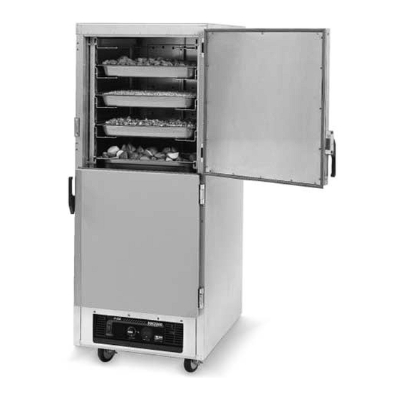
® ® InterMetro Industries Corporation Wilkes-Barre, PA 18705 570-825-2741 199 Series Rev. 3 USER MANUAL FOR THE METRO C199 AND FL199 SERIES INSULATED HEATED CABINETS Recommended Food Holding Guidelines Listed on pages 5 & 6. -
Page 2: Table Of Contents
Cabinet Model No. ________________________ Module Model No. _________________________ Module Serial No. _________________________ Slide Rack Model No. ______________________ SAMPLE OF CABINET LABELING C199-HM2000 = Full Height, Holding PAGE C199T-HM2000 = FL199-HM2000 = Full Height, High Humidity Holding FL199H-HM2000 = SAMPLE OF SLIDE RACK... -
Page 3: Features
• Clearly-marked control panel for easy viewing and allowing climate adjustments without opening the door(s). • Removable water pan (C199) or water bottle (FL199). • Rear pan stop. • Field reversible insulated and gasketed door(s). -
Page 4: C1. Hm2000 Holding Module
CVSN/-T/-H — Model V (adjustable) The Model V Slide Rack can be installed in either an inboard or outboard position. Center spacing on slides can be either 3" or 4 ". Slides can be removed by lifting upward and sliding the rivet heads out of the keyhole slots. -
Page 5: C2. Fl2000 High Humidity Holding
It is not necessary at the end of the operating day to disrupt the TEMPERATURE setting in order to turn the unit OFF. By switching the POWER switch to OFF, the unit is no longer operating. By switching the POWER switch to ON when resuming operations, the cabinet setting will be at the previous set point. -
Page 6: Food Holding Guidelines
9. To install the module, reverse step 8. When installing the module into the cabinet, the cord must be fed through the opening in the cabinet back panel. Be careful that the seals on the side of the module go inside the module slides. -
Page 7: Food Holding Guidelines
III. FOOD HOLDING GUIDELINES A. HM2000/HM15LW Recommended Food Holding Guidelines Food Product Baked Fish Baked Potatoes Biscuit Broccoli Chicken Nuggets Corn on the Cob Croissants Egg Patties French Fries** Fried Chicken Fried Fish Hamburgers Lasagna Mashed Potatoes Mixed Veggies Pancakes Pasta Peas Pizza... -
Page 8: V. Maintenance A. Cabinet Maintenance
ALLOW THE UNIT TO COOL BEFORE CLEANING, AS THE INTERIOR OF THE CABINET MAY BE HOT ENOUGH TO BURN. ALSO ALLOW THE WATER IN THE PAN (C199) OR BOTTLE (FL199) TO COOL BEFORE REMOVAL. 3. Open the door(s) and remove the slide racks and chimney. -
Page 9: A. Cabinet
VI. REPLACEMENT PARTS, PROCEDURES AND WIRING DIAGRAMS A. CABINET — ALL MODELS Refer to the Cabinet Replacement Parts Diagram on next page to identify the replacement parts. C199 Series Cabinet Replacement Parts Diagram (see page 9 for parts list) -
Page 10: Cabinet
CABINET REPLACEMENT PARTS LIST & height cabinet parts not shown) Item No. Part No. RPC199P-1102T RPC199P-1102B RPC199HP-1102 RPC199TP-1102 RPC06-809 RPC06-811 RPC06-810 RPC14-118 RPC14-119 C4SC C4SC-T C4SC-H C8SN C8SN-T C8SN-H CVSN CVSN-T CVSN-H RPC175-1108 RPC199H-1108 RPC199T-1108 B5DNB B5DN RPC06-179A RPC13-106 RPCAB-HBMPR RPC06-067 RPHANG-KIT Description... -
Page 11: Modules
B. MODULE Your module has been designed to be user- servicable, assuming a basic knowledge of the operation of electrical devices. This section has been written to guide the user step by step, and in layman’s terms, through the dismantling and servicing of the module. Before attempting to service your module, read the appropriate Module Repair Procedures (found elsewhere in this section) -
Page 12: Module Replacement Parts Diagram
Holding Module Replacement Parts Diagram REPLACEMENT PARTS LIST Item No. Part No. Description RPC13-017 Power Cord — 15 AMP (HM15LW only) RPC13-083 Strain Relief — 15 AMP (HM15LW only) RPC06-313 Thermostat Knob RPHM20-PAN Water Pan RPC13-127 Power Switch RPC13-129 Temperature Thermostat RPC13-105 Yellow Indicator Light RPHM20-2103... -
Page 13: Wiring Schematic
VI. WIRING SCHEMATICS HOLDING WIRING DIAGRAM... -
Page 14: Replacement Parts List
FL2000 High Humidity Module Replacement Parts Diagram AIR INTAKE COVER CONTROL PANEL COVER REPLACEMENT PARTS LIST Item # TOP PAN THERMOMETER SENSOR THERMOSTAT BULB Part # Description RPC13-099 Power Cord — 20 AMP RPC13-098 Strain Relief — 20 AMP RPC06-746 Knob RPC13-132 Power Switch... -
Page 15: Wiring Schematic
FL2000 HIGH HUMIDITY MODULE WIRING DIAGRAM... - Page 16 Thank you for purchasing a Metro Mobile Heated Cabinet. We are certain you will be more than satisfied with its quality and performance. Please fill in the warranty information space below so we may register your warranty. Also, so that we may learn more about our customers and hopefully be of continued service in the future, please take a moment to fill in the customer information space below.
- Page 17 STAPLE HERE...
- Page 18 Warranty ® InterMetro Industries Corporation...
- Page 19 L01-386 InterMetro Industries Corporation Rev. A 03 ® North Washington Street, Wilkes-Barre, PA 18705 Information and specifications are subject to change without notice. Please confirm at time of order. For Product Information Call: 1-800-433-2232 Visit Our Web Site: www.metro.com...
Need help?
Do you have a question about the C199 Series and is the answer not in the manual?
Questions and answers