
Related Manuals for Mitsubishi Electric XD8500U


Summary of Contents for Mitsubishi Electric XD8500U
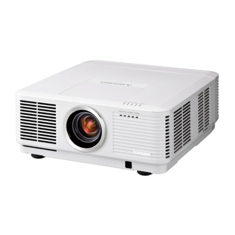
- Page 1 DLP™ PROJECTOR MODEL XD8500U User Manual XD8500 This User Manual is important to you. Please read it before using your projector.
- Page 2 CAUTION RISK OF ELECTRIC SHOCK DO NOT OPEN CAUTION : TO REDUCE THE RISK OF ELECTRIC SHOCK, DO NOT REMOVE COVER (OR BACK) NO USER-SERVICEABLE PARTS INSIDE REFER SERVICING TO QUALIFIED SERVICE PERSONNEL. The lightning flash with arrowhead symbol within an equilateral triangle is intended to alert the user to the presence of uninsulated “dangerous voltage”...
-
Page 3: Table Of Contents
Contents Important safeguards ........................4 Preparing your projector ........................6 Using the remote control ........................9 Setting up your projector .........................11 Viewing computer images .......................18 Viewing video images ........................24 Menu operation ..........................30 Adjusting projected images ......................43 Initial network settings ........................51 Lamp relay ............................55 Advanced features ..........................57 Replacing the lamp .........................64 Maintenance ............................67... -
Page 4: Important Safeguards
Important safeguards Please read all these instructions regarding your 10. Power sources projector and retain them for future reference. Follow This projector should be operated only from the all warnings and instructions marked on the projector. type of power source indicated on the marking label. - Page 5 Important safeguards (continued) Do not use the projector with condensation on it. WARNING: It can lead to breakdown or other failure. Unplug immediately if there is something Place of installation wrong with your projector. For safety’s sake, refrain from setting the projector at any Do not operate if smoke, strange noise or odor comes out place subjected to high temperature and high humidity.
-
Page 6: Preparing Your Projector
Preparing your projector Checking accessories The following accessories are provided with this projector. Check to be sure that all of the accessories are packed in the package. Cable Power supply parts Mini D-SUB 15-pin Mini D-SUB 15-pin Computer cable Power cord (two) (246C597-20) (246C684-10, 246C383-20) Remote control parts... -
Page 7: Terminal Panel
Preparing your projector (continued) Overview 1 Indicators 2 Intake vent/Filter cover 3 Exhaust vent 4 Lens 5 Remote control sensor (front) 6 Mitsubishi logo plate position (Put the plate according to the installation orientation.) 7 Intake vent 8 Control area 9 Terminal panel 10 Remote control sensor (rear) Caution:... -
Page 8: Bottom Side
Preparing your projector (continued) Indicators Bottom side 1 Lock bar (SECURITY ANCHOR) the projector. 2 Adjustment feet 1 FILTER indicator 2 STATUS indicator 3 LAMP 2 indicator 4 LAMP 1 indicator 5 POWER indicator Remote control 1 Indicator 2 POWER button (ON/STANDBY) The status is changed between ON and STANDBY. -
Page 9: Using The Remote Control
Using the remote control Operational range of the remote control Front of projector Rear of projector About 30° About 30° About 30° About 30° Operate the remote control within a distance of 30 m (98.4 feet) from the projector, pointing the light beam at the remote control photo-sensor (front or rear) of the projector. -
Page 10: Setting The Id Number Of The Remote Control
Using the remote control (continued) XX: Shows the ID number of the projector. Setting the ID number of the remote (When the PROJECTOR ID is “ALL,” “ALL” control is displayed.) You can control multiple projectors collectively or YY: Shows the current CONTROLLER ID. (When individually using one remote control by setting the ID the CONTROLLER ID is “ALL,”... -
Page 11: Setting Up Your Projector
Setting up your projector Before setting up Before setting up the projector, check the operating environment. If the environmental requirements are not satisfied, the projector may break down or fail. Setup environment The allowable operating temperature varies depending on the HIGH ALTITUDE mode setting. For use in the STANDARD mode, the allowable operating temperature is +41°F (+5°C) to +104°F (+40°C). -
Page 12: Adjusting The Position Of The Projected Image
Setting up your projector (continued) Setup adjustment SHIFT menu is displayed, the shift mode can be switched between FAST and STEP. When FAST How to turn on the projector is selected, the lens shifts in a large amount with When you have to turn on the projector for setup the , , ... -
Page 13: Correcting Skewed Or Distorted Image
Setting up your projector (continued) Setting HIGH ALTITUDE MODE Correcting skewed or distorted image For the best projection, project images on a flat screen 1 menu according to the altitude at which you use installed at 90 degrees to the floor. If necessary, tilt the the projector. - Page 14 Setting up your projector (continued) Adjustment using the KEYSTONE mode: performed, the displayed image may be distorted. When the screen and the projector are not placed perpendicularly to each other, projected images projector and the screen, a perfect rectangular become trapezoidal. If you cannot place them image and the proper aspect ratio may not be perpendicularly to each other, press the ENTER/ obtained.
-
Page 15: Adjustment Using The Curved Mode
Setting up your projector (continued) LOWER RIGHT, LOWER LEFT, UPPER RIGHT, or Adjustment using the CURVED mode UPPER LEFT menu To adjust images projected on a curved surface, press You can adjust the horizontal or vertical position of the the ENTER/GEOMETRY button on the projector or the selected corner. - Page 16 Setting up your projector (continued) Adjusting the origin to the horizontal arc the ARC is adjusted in the direction) (or the ARC is adjusted in the direction) Press the button. Press the button. Press the Press the ...
-
Page 17: Rear Projection
Setting up your projector (continued) Front projection, ceiling mounting Rear projection For ceiling mounting, you need the ceiling mount Ask a specialist for installation. For details, consult kit designed for this projector. Ask a specialist for your dealer. installation. For details, consult your dealer. damage caused by use of any non-recommended ceiling mount kit or installation of the ceiling mount kit in an improper location. -
Page 18: Viewing Computer Images
Viewing computer images A. Connecting the projector to a computer Preparation: monitor. Computer For analog connection: (For using the COMPUTER/COMPONENT VIDEO IN-1 terminal.) COMPUTER/ 1. Connect one end of the supplied computer cable to the COMPONENT COMPUTER/COMPONENT/VIDEO IN-1 terminal of the VIDEO IN-1 projector. - Page 19 Viewing computer images (continued) B. Plugging the power cord breaker to supply the power to the projector. If you do not have such outlet, ask your dealer to install it. 1. Plug the attached power cord into the power cord inlet of this projector.
- Page 20 Viewing computer images (continued) Attaching the power cord holder: To reduce the risk of accidental disconnection of the power cord from the projector, attach the supplied power cord holder to hold it. Important: Once the power cord holder is attached to the projector, it cannot be removed.
- Page 21 Viewing computer images (continued) C. Projecting images Preparation: POWER button POWER button (ON/STANDBY) (ON/STANDBY) LAMP 2 indicator POWER indicator COMPUTER 1, 2 buttons LAMP 1 indicator , , , buttons DVI-D(HDCP) button ENTER button COMPUTER/DVI-D button , , , buttons ENTER button LENS SHIFT button ZOOM/FOCUS button...
-
Page 22: To Stop Projecting
Viewing computer images (continued) 9. Press the ZOOM/FOCUS button to display the ZOOM/FOCUS menu. 10. Adjust with the or button to get an approximate size. switched between FAST and STEP. When FAST is selected, the speed of zoom controlled by the or button becomes fast, and it becomes slow when STEP is selected. - Page 23 Viewing computer images (continued) Blanking the screen temporarily (BLANK) The video signal is temporarily muted when the BLANK button is pressed. The screen turns black. To cancel muting, press the BLANK button again. AUTO POSITION button When the image supplied from the computer is displaced, carry out the following procedure. 1.
-
Page 24: Viewing Video Images
Viewing video images A. Connecting the projector to video equipment Preparation: Make sure that the power of the projector and that of the video equipment are turned off. Connecting to a video player, etc. 1. Connect one end of a commercially available BNC cable to Video player, or the like BNC cable (option) the VIDEO IN terminal of the projector. - Page 25 Viewing video images (continued) Projector + DVD player or HDTV decoder Some DVD players have an output connector for 3-line fitting (Y, C ). When connecting such DVD player with this projector, use the COMPUTER/COMPONENT VIDEO IN-2 terminals. DVD player or HDTV decoder BNC-RCA connector (option) COMPUTER/COMPONENT VIDEO IN-2...
- Page 26 Viewing video images (continued) Connection (for video equipment having a DVI-D terminal) Equipment having a DVI-D terminal To DVI-D terminal COMPUTER/COMPONENT VIDEO DVI-D IN (HDCP) DVI cable (option) When you connect this projector and a digital device (such as a DVD player) via the HDMI IN or COMPUTER/ COMPONENT VIDEO DVI-D IN (HDCP) terminal, black color may appear dark and deep, depending on the type of the connected device.
- Page 27 Viewing video images (continued) C. Projecting images Preparation: POWER button (ON/STANDBY) POWER button (ON/STANDBY) LAMP 2 indicator POWER indicator HDMI button LAMP 1 indicator COMPUTER 1, 2 buttons VIDEO button , , , buttons S-VIDEO button DVI-D(HDCP) button COMPUTER/DVI-D button ENTER button VIDEO/HDMI button , , , ...
-
Page 28: Setting The Aspect Ratio
Viewing video images (continued) 7. Adjust the position of the projector to keep an appropriate projection distance with which images are projected in their specified sizes. 8. Adjust the position of the projector so that the projector and the screen are perpendicular to each other. (See page 11.) 14.) 9. -
Page 29: Setting The Screen Size
Viewing computer images (continued) Setting the screen size Change the setting of the SCREEN according to the type of the screen to be used. (See page 31 for menu setting.) opt. 1. Display the INSTALLATION 2 menu. INSTALLATION 2 2. Select SCREEN by pressing the or button. AUTO POWER ON 3. -
Page 30: Menu Operation
Menu operation You can make various settings using the displayed menus. Following 8 menus are displayed. IMAGE menu (page 32) INSTALLATION 1 menu (page 34) INSTALLATION 2 menu (page 35) opt. opt. opt. INSTALLATION 1 IMAGE INSTALLATION 2 COLOR ENHANCER AUTO LAMP MODE STANDARD... -
Page 31: How To Set The Menus
Menu operation (continued) How to set the menus 1. Press the MENU button. Selectable menus are displayed by icons. (The menu icon being selected is displayed on a blue background.) opt. IMAGE The name of the menu being selected is displayed. 2. - Page 32 Menu operation (continued) IMAGE menu opt. opt. IMAGE IMAGE ADVANCED MENU COLOR ENHANCER AUTO NOISE REDUCTION SUPER RESOLUTION CONTRAST INPUT LEVEL BRIGHTNESS CLOSED CAPTION COLOR MATRIX COMPUTER DEMO MODE COLOR TEMP. STANDARD COLOR TINT SHARPNESS ADVANCED MENU ENTER ITEM SETTING FUNCTION COLOR ENHANCER AUTO...
- Page 33 Menu operation (continued) be adjusted. MANUAL or MEASURE. In this case, you cannot set any other items than MULTI-SCREEN. addition, the vertical line of the colored characters may be blurred. terminal of the connected device. North America. EN-33...
- Page 34 Menu operation (continued) INSTALLATION 1 menu opt. opt. INSTALLATION 1 INSTALLATION 1 LENS LOCK LAMP MODE STANDARD ZOOM/FOCUS LOCK LAMP SELECT DUAL LAMP RELAY 1H/24H LENS SHIFT LOCK STANDBY MODE LENS SHIFT RESET IMAGE REVERSE HIGH ALTITUDE MODE STANDARD LENS LOCK ENTER ITEM SETTING...
- Page 35 Menu operation (continued) INSTALLATION 2 menu opt. INSTALLATION 2 AUTO POWER ON AUTO POWER OFF 5min SCREEN SETUP IMAGE CAPTURE SPLASH SCREEN BACK COLOR BLUE DVI LONG CABLE AUTO REMOTE 1 MODE ENTER ITEM SETTING FUNCTION AUTO POWER ON ON / OFF When ON is chosen, the projector is automatically turn on when the power cord is plugged in the wall outlet.
- Page 36 Menu operation (continued) MULTI-SCREEN menu opt. MULTI-SCREEN EDGE BLENDING SETTING EDGE ADJUST COLOR MATCHING MANUAL SETTING MEASURE MEASURED DATA ITEM SETTING FUNCTION EDGE BLENDING Select when using the projector alone. Select when using the projector to configure the multi-screen consisting of multiple projectors.
- Page 37 Menu operation (continued) FEATURE menu opt. opt. FEATURE FEATURE PROJECTOR ID ADVANCED MENU GROUP ID AUTO VIDEO SIGNAL PASSWORD FUNCTION DISPLAY INPUT SETUP AUTO MENU POSITION SCART INPUT CINEMA MODE LAMP WARNING AUTO STANDARD HIDE OSD LANGUAGE English Ë ADVANCED MENU ENTER LAMP 1 TIME RESET RESET ALL...
- Page 38 Menu operation (continued) FEATURE menu (continued) ITEM SETTING FUNCTION LAMP 1 TIME RESET OK The LAMP 1 operation time is reset to 0. LAMP 2 TIME RESET OK The LAMP 2 operation time is reset to 0. RESET ALL The menu settings are reset to the factory defaults (except the LANGUAGE, PASSWORD FUNCTION, IMAGE CAPTURE, SCREEN, and NETWORK settings).
- Page 39 Menu operation (continued) SIGNAL menu opt. opt. opt. SIGNAL SIGNAL SIGNAL RESOLUTION (MEMORIZE) USER MEMORY CALL AUTO VERTICAL 60.00 Hz SIGNAL MEMORY MEMORIZE CLAMP POSITION FREQUENCY RESOLUTION HORIZONTAL 48.36 KHz CLAMP WIDTH 1024 x 768 (MEMORIZE FREQUENCY 1024 HORIZ. POSITION HORIZ.
- Page 40 Menu operation (continued) ITEM SETTING FUNCTION ASPECT NORMAL Input video signal is displayed at the max height (768 pixels) or max width (1024 pixels) of the panel while its aspect ratio is maintained. When SCREEN is 16:9, the input video signal is displayed at the max height (576 pixels) or max width (1024 pixels) of the panel.
- Page 41 Menu operation (continued) NETWORK menu opt. opt. NETWORK NETWORK IP CONFIG PROJECTOR NAME NETWORK DHCP CERTIFICATION NETWORK ENTER IP ADDRESS 0. 0. 0. 0 PASSWORD IP CONFIG SUBNET MASK 0. 0. 0. 0 ENTER DEFAULT GATEWAY CONTROL SYSTEM 0. 0. 0. 0 STANDARD MAC ADDRESS NETWORK RESET...
- Page 42 Menu operation (continued) INFORMATION menu opt. INFORMATION LAMP 1 TIME (LOW) **** LAMP 2 TIME (LOW) **** NEXT LAMP RELAY SERIAL NUMBER ******** INPUT COMPUTER1 RESOLUTION 1024 x 768 VERTICAL 60.00 Hz FREQUENCY HORIZONTAL 48.36 kHz FREQUENCY SYNC. TYPE 5 WIRE ITEM DESCRIPTION LAMP 1 TIME (LOW)
-
Page 43: Adjusting Projected Images
Adjusting projected images To adjust the brightness (CONTRAST and BRIGHTNESS): You can make adjustments for the brightness of the projected image using the menu. (See page 31 for menu setting.) 1. Display the IMAGE menu. 2. Select CONTRAST or BRIGHTNESS by pressing the or button. 3. -
Page 44: About Color Temperature
Adjusting projected images (continued) To cancel the menu: 7. Press the MENU button. To enable the stored color temperature: 1. Set COLOR TEMP. to USER in the IMAGE menu. About color temperature Color temperature is a way to show the differences in white. White of which temperature is low appears reddish. When the color temperature rises, white appears bluish. - Page 45 Adjusting projected images (continued) Adjusting the fineness of the image (SUPER RESOLUTION): You can adjust the fineness of the image using the menu. (See page 31 for menu setting.) With the IMAGE menu: 1. Display the IMAGE menu. SUPER RESOLUTION 2.
-
Page 46: Saving The Setting In The Signal Memory
Adjusting projected images (continued) ZOOM(V) HORIZ. POSITION Use to adjust the horizontal position of the projected image. The setting range is -999 to +999. VERT. POSITION Use to adjust the vertical position of the projected image. The setting range is -999 to +999. RASTER POSITION(H) When the supplied image is not projected on the entire display area, the horizontal location of the projected image can be adjusted within the area. -
Page 47: How To Adjust The Computer Image
Adjusting projected images (continued) How to adjust the computer image This projector automatically selects a proper signal format according to the type of video signal supplied from the computer. However, video signals from the computer may not be projected correctly depending on the types of the computer and images to be projected. - Page 48 Adjusting projected images (continued) How to adjust the image supplied from the computer using the menu: Carry out the following procedures according to the symptoms. Wide strips appear. ……………………………………… Adjust TRACKING in the SIGNAL menu. The projected image flickers. The projected image is blurred........Adjust FINE SYNC. in the SIGNAL menu. The projected image is displaced horizontally.
- Page 49 Adjusting projected images (continued) 11. Press the ENTER button. Adjusting the image displayed on SETTING - BLACK LEVEL the multi-screen INTERLOCKED You can configure a multi-screen display using multiple projectors. GREEN You can make the joints of the images displayed on BLUE the projectors unnoticeable and adjust the differences 12.
-
Page 50: Adjusting The Color Variations
Adjusting projected images (continued) 7. Select an item you want to set by pressing the or Adjusting the color variations button. You can adjust the variations in the colors of the images displayed on multiple projectors using the COLOR. -
Page 51: Initial Network Settings
Initial network settings You can set the network of the projector using the menu. selecting OK or CANCEL. opt. Enabling or disabling the network NETWORK PROJECTOR NAME certification NETWORK CERTIFICATION You can select whether or not to certify the network NETWORK ENTER PASSWORD... -
Page 52: Ip Address Settings
Initial network settings (continued) CLEAR key: ..Deleting all the entered IP Settings characters. (See page 31 for menu setting.) 1. Display the NETWORK menu. buttons (0 to 9) while holding down the NUM 2. Press the or button to select IP CONFIG. button on the remote control. -
Page 53: Saving Ip Config Settings
Initial network settings (continued) buttons (0 to 9) while holding down the NUM IP CONFIG menu is displayed. If the entered button on the remote control. content is not correct, the IP CONFIG menu is displayed after an error dialog is displayed. 5. -
Page 54: How To Use Network Function
Initial network settings (continued) Glossary Initialization of Network Settings For more detail of the glossary below, refer to the (See page 31 for menu setting.) technical book that is commercially available. 1. Display the NETWORK menu. Term Description 2. Press the or button to select NETWORK Abbreviation for Dynamic Host RESET. -
Page 55: Lamp Relay
Lamp relay Using the lamp relay function, you can project images 1H/24H continuously. The lamp relay function automatically rests or switches the lamps. The lamp relay is NEXT LAMP RELAY performed when LAMP SELECT in the INSTALLATION 2 3 H 1 menu is set to DUAL or SINGLE. - Page 56 Lamp relay (continued) 1 WEEK selection, or during the lamp relay operation, you cannot change the setting of LAMP SELECT and NEXT LAMP RELAY LAMP RELAY. 7 D 0 0 H deteriorate earlier unless they are turned off for 1 CLEAR hour per week.
-
Page 57: Advanced Features
Advanced features Changing the image displayed at the mode automatically. startup You can display your desired image as the startup screen (or splash screen). By setting the menu, you can use such image instead of the background image that is displayed when no video signal is supplied. CAPTURE : ENTER X2 CANCEL : MENU CAPTURE : ENTER + ENTER... -
Page 58: Password Function
Advanced features (continued) 7. Press the ENTER button. Password function To cancel the procedure, press the MENU This projector is equipped with the password function button. that is designed for prevention of wrong operation by 8. Enter the password again for confirmation using the children and restriction on operation by other than same steps. -
Page 59: Magnifying The Displayed Image
Advanced features (continued) Picture in Picture (PinP) Magnifying the displayed image One of the special features of this projector is the By pressing the MAGNIFY button on the remote picture-in-picture (PinP) mode. The PinP mode allows control, you can magnify the image to view the details. you to view the images from different sources at the same time. -
Page 60: Supervising And Controlling By Computer
Advanced features (continued) Important: Supervising and controlling by computer You can supervise and control the projector’s in the NETWORK menu, the web control for operation using a personal computer via a LAN. Crestron is enabled. For such control, Adobe Flash Major functions Player should be installed in advance. - Page 61 Setup window is returned. INF1? Inquiry about the manufacturer name “MITSUBISHI” is returned. INF2? Inquiry about the model name “XD8500U” is returned. INF0? Inquiry about other information No other information is available. No parameter is returned. CLSS? Inquiry about the class information “1”...
-
Page 62: Monitoring And Control Using Serial Terminal
Advanced features (continued) Monitoring and control using SERIAL terminal Using the SERIAL terminal, you can monitor and control multiple projectors collectively or individually. For details, contact your dealer. RS-232C cable (option) To RS-232C terminal RS-232C cable (option) RS-232C cable (option) To SERIAL To SERIAL To SERIAL... - Page 63 Advanced features (continued) Control by a control panel, etc. When installing the projector in a place where the remote control signals cannot reach the projector, you can control the projector using a control panel or other device connected to the REMOTE 1 IN terminal. External contact Remote control control...
-
Page 64: Replacing The Lamp
Replacing the lamp This projector is equipped with 2 lamps to project because of an impact, scratch, or deterioration through use. The period of time until explosion or images. This lamp is a consumable. It may burn out permanent failure to illuminate varies considerably or its brightness may decrease during use. - Page 65 Replacing the lamp (continued) 3. Loosen two screws (c) that are securing the lamp Reset of the lamp operation time box to be removed using a Phillips screwdriver. Reset the lamp operating time of the newly installed lamp. LAMP 2 LAMP 1 You can reset the lamp operation time using the menu.
- Page 66 Replacing the lamp (continued) When removing the lamp from the ceiling-mounted projector When removing the lamp from the ceiling-mounted projector, use the lamp replacement tray packed with the projector or option lamp to prevent glass fragments from scattering. 1. Follow steps 1 to 4 on pages 64 and 65. 2.
-
Page 67: Maintenance
Maintenance 6. Attach the filter holder (c). Cleaning of the filter Clean dust from the filter. Before cleaning the filter, be sure to turn off the power of the projector and unplug the power cord from the outlet. Clean the filter frequently (at least once a month). Dust settling on the filter causes the temperature 7. -
Page 68: Cleaning Of The Projector And The Vents
Maintenance (continued) Warning: Do not use flammable solvents (benzene, thinner, etc.) and flammable aerosols when cleaning the projector body and lens. Flammable substances may ignite causing fire or breakdown while the lamp is illuminating. Caution: Be sure to turn off the lamp and unplug the power cord from the wall outlet before you perform any maintenance on the projector. -
Page 69: Troubleshooting
Troubleshooting Before asking for repair of the projector, check the following. If the symptom persists, stop using the projector, be sure to unplug the power plug, and then contact your dealer. No image appears on the screen. Problem Solution Power can not be turned on. - Page 70 Troubleshooting (continued) No image appears on the screen. (continued) Problem Solution The screen for entering the password enable the password lock. Enter the password or contact the person in charge of management of the appears. projector. (See page 58.) “NO SIGNAL”...
- Page 71 Troubleshooting (continued) Images are not displayed correctly. (continued) Problem Solution Hue is not appropriate. INPUT setting in the SIGNAL menu on the projector, the entire screen may become reddish or greenish. YCbCr output setting of the external device even when the input source is other than COMPUTER (for example, when the input source is HDMI), the entire image appears reddish or greenish.
- Page 72 Troubleshooting (continued) Others (continued) Problem Solution “TEMPERATURE!!” is displayed. temperature stays high, the lamp goes out. Eliminate any causes of the rise in the ambient temperature. kept blocked, the lamp goes out. Remove the objects blocking the intake or exhaust vents. mark appears.
-
Page 73: Indicators
Indicators This projector has 5 indicators, each of which shows the operation condition of the projector. The following offer solutions to possible problems. If these problems persist, turn the projector off and consult your dealer. POWER indicator FILTER indicator LAMP 1 indicator STATUS indicator LAMP 2 indicator ... -
Page 74: Specifications
Specifications The specifications and outside appearance of the projector are subject to change without prior notice. Type DLP™ projector Model XD8500U Display technology 0.7-inch Single chip DMD Pixel 1024 x 768 = 786432 pixels Projection lens F 2.0 - 2.4 f= 24.5 - 33.1 mm... - Page 75 Specifications (continued) Specification of RGB signals in each computer mode of the projector Plug and Play *3 Horizontal Vertical Normal COMPUTER / COMPUTER / Resolution Signal mode frequency frequency mode COMPONENT COMPONENT HDMI IN (H x V) (kHz) (Hz) (H x V) VIDEO IN-1 DVI-D IN (HDCP) terminal...
- Page 76 Specifications (continued) Specification of RGB signals in each computer mode of the projector (continued) respectively. When these signals are supplied to the VIDEO IN or S-VIDEO IN terminal, the signal Important: mode is indicated as TV60 or TV50. When they are Some computers aren’t compatible with the supplied to the COMPUTER/COMPONENT VIDEO projector.
- Page 77 Specifications (continued) Specification of the attached lens With ultra short throw zoom lens (OL-XD8000EZ) F No. F2.4 Focal distance f = 11.4 - 14.2 mm Zoom/focus Electrical drive Picture size 40 inch (81 cm X 61 cm) - 300 inch (610 cm X 457 cm) Screen size (4:3) Projection distance (L) Lens shift height...
- Page 78 Specifications (continued) With tele throw zoom lens (OL-XD2000TZ) F No. F2.2 - 2.7 Focal distance f = 40.7 - 65.1 mm Zoom/focus Electrical drive Picture size 40 inch (81 cm X 61 cm) - 300 inch (610 cm X 457 cm) Screen size (4:3) Projection distance (L) Lens shift height...
- Page 79 MITSUBISHI ELECTRIC CORPORATION 1 Zusho Baba, Nagaokakyo-City, Kyoto Japan...
Need help?
Do you have a question about the XD8500U and is the answer not in the manual?
Questions and answers