Table of Contents
Advertisement
Quick Links
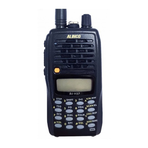
144/430MHz DUAL BAND FM TRANSCEIVER
DJ-V57
Instruction Manual
Thank you for purchasing your new Alinco transceiver. Please read this manual
carefully before using the product to ensure full performance, and keep this manual for
future reference as it contains information on after-sales service.
In case addendum or errata sheets are included with this product, please read those
materials and keep them together with this instruction manual for future reference.
ALINCO, INC.
Advertisement
Table of Contents

Related Manuals for Alinco DJ-V57


Summary of Contents for Alinco DJ-V57
-
Page 1: Instruction Manual
144/430MHz DUAL BAND FM TRANSCEIVER DJ-V57 Instruction Manual Thank you for purchasing your new Alinco transceiver. Please read this manual carefully before using the product to ensure full performance, and keep this manual for future reference as it contains information on after-sales service. -
Page 2: Notice / Compliance Information Statement
FOR HOME OR OFFICE USE Information in this document is subject to change without notice or obligation. All brand names and trademarks are the property of their respective owners. Alinco cannot be liable for pictorial or typographical inaccuracies. Some parts, options and/or accessories are unavailable in certain areas. - Page 3 NOTICE / Compliance Information Statement Conformity Information Alinco, Inc. Electronics Division hereby declare on our sole responsibility that the product(s) listed below comply the essential requirements of the Directive 1999/5/EC, The council of 3/9/99 on Radio Equipment and Telecommunication Terminal...
-
Page 4: Table Of Contents
Contents Contents NOTICE / Compliance Information Statement ..........2 Contents ......................4 Warning.......................7 Introduction ......................12 Before transmitting..................12 1.Features ......................13 Accessories ......................13 2.Accessories ....................14 Installations ......................14 2.1.1 Antenna ......................14 2.1.2 Hand Strap....................14 2.1.3 Belt Clip .....................14 2.1.4 Battery Pack ....................15 2.1.5 Prevent Short Circuiting the Battery Pack ..........18 3.Names and Operations of Parts ..............19 Names and Operations of Keys and Ports............19 Keypad ........................21... - Page 5 Contents Call-Channel Mode.....................31 Receiving ......................31 4.8.1 Monitor Function..................32 Transmitting......................32 4.9.1 Selecting the Output Level .................32 5.Useful Functions ...................33 Scan Modes......................33 5.1.1 VFO-Scan....................33 5.1.2 Memory-Scan .....................33 5.1.3 Setting Skip Channels ................34 Keylock .......................34 Tone-Burst ......................34 Naming Memory Channels .................35 5.4.1 Setting Name-Tag..................35 5.4.2 Using the Channel Name Function ............35 Lamp ........................35...
- Page 6 Contents 8.Set Mode......................45 Set Mode Operation ....................45 Entering the Set Mode ..................45 Available Parameters ..................46 8.3.1 Menu 1 Battery Save (BS) Function ............46 8.3.2 Menu 2 Timer/Busy Scan Setting ..............46 8.3.3 Menu 3 Beep Function ................46 8.3.4 Menu 4 VOX delay time setting..............46 8.3.5 Menu 5 Auto-Power-Off Setting..............47 8.3.6...
-
Page 7: Warning
Warning Warning To prevent any hazard during operation of Alincon's radio product, in this manual and on the product you may find symbols shown below. Please read and understand the meanings of these symbols before starting to use the product. This symbol is intended to alert the user to an immediate danger that Danger may cause loss of life and property if the user disregards the warning. - Page 8 Warning Do not use multiple radios in very close proximity. It may cause interference and/or damage to the product(s). Risk of explosion if battery is replaced with an incorrect type. Dispose of, or recycle used batteries according to your local regulations. The manufacturer declines any responsibilities against loss of life and property due to a failure of this product when used with or as a part of a device made by third parties.
- Page 9 Warning Do not handle a power supply with a wet hand. It may result in electric shock. Securely plug the power supply to the wall outlet. Insecure installation may result in short-circuiting, electronic shock and/or fire. Do not plug the power supply into the wall socket if the contacts are dirty. Short-circuit and/or overheating may result in fire, electric shock and/or damage to the product.
- Page 10 Warning Caution Environment and condition of use Do not use the product in proximity to a TV or a radio. It may cause interference or receive interference. Do not install in a humid, dusty or insufficiently ventilated place. It may result in electric shock, fire and/or malfunction.
- Page 11 10 kA.). Note also that no car provides adequate protection of its passengers or drivers against lightning as well. Therefore, Alinco will not take responsibility for any danger associated with using its hand-held radios outdoor or inside the car during lightning.
-
Page 12: Introduction
Introduction / Before transmitting Introduction Thank you very much for purchasing this excellent Alinco transceiver. Our products are ranked among the finest in the world. This radio has been manufactured with state of the art technology and it has been tested carefully at our factory. It is designed to operate to your satisfaction for many years under normal use. -
Page 13: Features
1.Features 1. Features This transceiver has the following main features. 144/430MHz dual-band handheld transceiver Choice of 3 power output levels (5/2/0.5W) Quick-write memory channels Direct frequency input through illuminated keypad High-grade water-resistant materials compatible to IPX7 * Rugged polycarbonate body resists dirt and dust Great audio with large 40mm internal speaker 39 CTCSS tone squelch (encode + decode) and 104 DCS Search-scan (programmed scanning) available on each band... -
Page 14: Accessories
2.Accessories 2. Accessories Installations 2.1.1 Antenna Attaching the Antenna 1. Hold the antenna by its base. 2. Align the grooves at the base of the antenna with the protrusions on the antenna connector. 3. Slide the antenna down and turn it clockwise until it stops. -
Page 15: Battery Pack
2.Accessories 2.1.4 Battery Pack For the specifications and the charging procedures, please refer to "Battery Packs"(page 59) and "Using the Chargers"(page 60). Attaching the Battery Pack Align the catches on the battery pack with the Catch grooves on the unit, and close the latch until it clicks. Latch Groove Removing the Battery Pack... - Page 16 2.Accessories Caution • Risk of explosion, generation of heat or leak of chemicals inside if the battery is replaced by an incorrect type. Use always the recommended types of batteries in this manual only. • The battery pack isn't fully charged when shipped. It must be charged before use.
- Page 17 2.Accessories Charging the Battery Pack Using DC-Jack on the Unit The unit can charge the EBP-65 and EBP-66 optional Ni-MH battery packs by supplying DC power through the DC-jack on the unit using EDC-146/147/148 wall chargers or an optional DC power supply (DC 12V~DC 16V, 1A or more: IEC/EN 60950-1 compliant) and a DC cable such as EDC-37.
-
Page 18: Prevent Short Circuiting The Battery Pack
2.Accessories 2.1.5 Prevent Short Circuiting the Battery Pack Be extra cautious when carrying the rechargeable battery pack; short circuiting will produce surge current possibly resulting in fire. DON'T carry with DON'T carry the battery DON'T place in the metals of any type, e.g. pack inside bags made proximity of metals or chains. -
Page 19: Names And Operations Of Parts
3.Names and Operations of Parts 3. Names and Operations of Parts Names and Operations of Keys and Ports Top and Front Dial Rotate the dial to select the frequency of operation, memory channel, offset frequency, tone frequency, DCS code, Set mode settings, and the characters for name-tags. - Page 20 3.Names and Operations of Parts Side Antenna side Dial side SMA Antenna Attach the whip antenna. If you plan to use an optional antenna, Connector select one that is tuned to the operating frequency. FUNC key The FUNC key is used in combination with the other keys to access the various functions of the unit.
-
Page 21: Keypad
3.Names and Operations of Parts Keypad Without pressing the FUNC key. While appears after the FUNC key is pressed. Inputs 1. Channel step setting (page 26). Inputs 2. Offset frequency setting (page 27). Inputs 3. Alert Function (page 43). Inputs 4. Tone Encode / Tone Squelch setting (page 36). -
Page 22: Display (Lcd)
3.Names and Operations of Parts Display (LCD) Appears when the FUNC key is pressed. Indicates the shift (+/-) direction. Appears when setting the CTCSS tone encoder. Appears when setting the tone squelch. Appears when setting the VOX. Appears when setting the DCS. Appears when setting the NFM. -
Page 23: Basic Operation
4.Basic Operation 4. Basic Operation Turning On the Power Hold the key down for a second. To turn off the power, hold the key down until the display turns off. Adjusting the Audio Output (Volume) • There are 31 audio output levels (00~30). •... -
Page 24: Operating Modes
4.Basic Operation Operating Modes This DJ-V57 has three operating modes: VFO mode, Memory mode and CALL mode. The VFO mode allows to operate at the displayed frequency. The Memory mode has 200 channels (VHF/UHF mixture) and the CALL mode has one VHF and one UHF channel. -
Page 25: Setting The Frequency In The Vfo Mode
4.Basic Operation Setting the Frequency in the VFO Mode The factory default of this unit is the VFO mode. The VFO mode allows you to change the frequency and operating parameters by using the dial and key operations. 4.5.1 Setting the Frequency To Select the VFO Mode key switches between the VFO and Memory mode each time the key is pressed. -
Page 26: Setting The Tuning Step
4.Basic Operation Tuning step Entry completion digit Final digit selection 5.0kHz 1kHz Accept 0 or 5 as valid number. 10.0kHz 10kHz Accept any of 0 to 9 keys. 12.5kHz 10kHz When you input the 10kHz digit, the 1kHz digit is set automatically as follows. -
Page 27: Shift Direction And Offset Frequency Settings
4.Basic Operation 4.5.3 Shift Direction and Offset Frequency Settings In conventional repeater systems, a signal received on one frequency is retransmitted on another frequency. The difference between these two frequencies is called the offset frequency. The selectable offset frequency of this unit is from 0 to 99.995MHz. 1. -
Page 28: Memory Mode
4.Basic Operation Memory Mode This mode allows recalling and operating the preprogrammed frequency or setting in the memory channels. This unit provides up to 200 memory channels, 2 CALL channel (VHF/UHF), 2 Repeater-Access function memory (VHF/UHF), 10 Transmitter Detecting Function memory and 2 Program scan edge memory (VHF/UHF). 4.6.1 How to Program Memory Channel(s) 1. -
Page 29: Quick Program Memory Channel(S)
4.Basic Operation 4.6.4 Quick Program Memory Channel(s) This function is to quickly write in the memory. 1. Select a frequency and operating parameters to be programmed in the VFO mode. 2. Press the key for more than 2 seconds. 3. The memory number blinks and a beep sounds. NOTE: This function can't be used if all memory channels are already programmed. -
Page 30: Programming A Repeater-Access Function Setting
4.Basic Operation 4.6.6 Programming a Repeater-Access Function Setting The "Repeater-Access" function is to set the desired shift and tone parameters to the current operating frequency by just 2 key-touches. Please set the parameters to be applied to the Repeater-Access function here. 1. -
Page 31: Call-Channel Mode
4.Basic Operation Call-Channel Mode This mode is used to recall a most frequently used memory channel (stored in MC channel) with a single key-touch. 1. Press the key. " " is displayed on the LCD, and the channel programmed in MC is recalled. 2. -
Page 32: Monitor Function
4.Basic Operation 4.8.1 Monitor Function In case the receiving signal is weak and the audio is intermittently cut off by the squelch, press the MONI key. As long as this key is pressed, the squelch including TSQ/DCS unmutes making the audio easier to hear. •... -
Page 33: Useful Functions
5.Useful Functions 5. Useful Functions Scan Modes The scan function automatically searches the receiving signals. There are 2 modes for scan-resume condition. • Busy Scan: The scan stops when a signal is detected, stays until the signal is gone then resumes scanning. •... -
Page 34: Setting Skip Channels
5.Useful Functions 5.1.3 Setting Skip Channels You can select the memory channels that you wish to skip during the memory-scan. • Press the FUNC key in the Memory mode, and while is displayed, press the key to set the currently selected memory channel as a skip channel. Use the same procedure to clear the skip channel setting. -
Page 35: Naming Memory Channels
5.Useful Functions Naming Memory Channels In the Memory mode, it is possible to display up to 7 alphanumeric characters (Name- tag) instead of conventional frequency display. 5.4.1 Setting Name-Tag 1. Select the memory channel. 2. Press the FUNC key, and while is displayed press the key. -
Page 36: Selective Calling
6.Selective Calling 6. Selective Calling Selective Calling Operations • To communicate only with selected stations, use either the Tone Squelch or the DCS function. The Tone Squelch function unmutes the squelch only when a signal added with one of the matching 39 CTCSS tone frequencies is received. •... -
Page 37: Switching Off The Tone Squelch
6.Selective Calling 6.1.2 Switching Off the Tone Squelch Press the key in Tone Squelch Setting mode to select TCS-OF, then press any key other than the MONI key to complete the setting. 6.1.3 To Differentiate the ENC/EDC Tones It is possible to set the encode and decode tones independently in the Tone Squelch Setting mode. -
Page 38: Changing The Dcs Code
6.Selective Calling 6.2.2 Changing the DCS Code 1. Rotate the dial in DCS Code Setting mode (while " " is displayed). 2. Press any key other than the MONI key to complete the setting. • The same DCS code is set for ENC/DEC, differential setting isn't available. One of the following 104 DCS codes can be selected. -
Page 39: Dtmf Tone Encoding
6.Selective Calling Advantage of DET It enables DCS squelch operation even in poorer signal conditions. Disadvantage of DET When it is activated, suppose 2 stations are sharing the same channel and using the DCS selective-calling technique and transmitting at the same time. After station A with its corresponding DCS is gone, you may still hear station B even his DCS code is different from A, although he can't open your DCS squelch by his signal alone. -
Page 40: Auto Dialer
6.Selective Calling Auto Dialer The DTMF tones can be stored in the memory to automatically transmit. 6.4.1 Setting the Auto Dialer • All 16 DTMF tones up to 16 characters are available for each of 9 memories and "M st" memory called an Auto Dialer memory. Programming the Auto Dialer Memories 1. -
Page 41: Redial (While Receiving)
6.Selective Calling 6.4.3 Redial (While Receiving) This function generates the last DTMF tones used by the unit. 1. Press the FUNC key, and while is displayed on the LCD, press the key. 2. Press the key. The last DTMF tones (either the auto dialer code or a manually input DTMF code) is automatically generated from the speaker. -
Page 42: Special Functions
7.Special Functions 7. Special Functions Repeater-Access 1. In the VFO/Memory/Call channel mode, select the channel to which you wish to apply the Repeater-Access setting. 2. Press the FUNC key, and while is displayed on the LCD, press the key. The Repeater-Access setting is applied to the operating frequency. NOTE: Preset parameters on the Repeater-Access function memory will be effective at any frequency. -
Page 43: Vox
7.Special Functions This function allows to transmit without using the PTT by simply speaking into the microphone. When you have stopped speaking, the unit will return to receive. 1. Press the FUNC key and while is displayed on the LCD, press the key to display the VOX setting. -
Page 44: Battery Type Setting
7.Special Functions Battery Type Setting Select the correct battery type from Ni-MH battery pack, Li-ion battery pack and Alkaline dry cells in order to display the battery-level icon correctly and to perform the battery-charge using the DC-jack. 1. Press the key for more than 2 seconds. -
Page 45: Set Mode
8.Set Mode 8. Set Mode The Set mode is used to customize the various operational parameters of your DJ-V57. Set Mode Operation This chart shows the available parameters in the Set mode. Menu Default setting Function BS-1 Battery save TIMER1... -
Page 46: Available Parameters
8.Set Mode Available Parameters 8.3.1 Menu 1 Battery Save (BS) Function This function prevents useless battery consumption by switching the power ON/OFF at a fixed ratio if there is no key operation or receiving signal for a continuous period of 5 seconds or more. 1. -
Page 47: Menu 5 Auto-Power-Off Setting
8.Set Mode 8.3.5 Menu 5 Auto-Power-Off Setting This function prevents the batteries from being exhausted when you forget to switch off the power. 1. APO-OF is displayed on the LCD. 2. The auto power off setting will change between ON and OFF when the dial is turned. -
Page 48: Menu 8 Clock Shift Setting
8.Set Mode 8.3.8 Menu 8 Clock Shift Setting In the unlikely event that you may hear a weak noise always on the same frequency, it may be so-called a CPU-clock noise. Unfortunately this is due to the circuit-design of this product and can't be eliminated, but can be moved away to another frequency. 1. -
Page 49: Menu 10 Tone-Burst Frequency Setting
8.Set Mode 8.3.10 Menu 10 Tone-Burst Frequency Setting 1. 1750 is displayed on the LCD. 2. Rotate the dial to select the tone-burst frequency. 1750 2100 1000 1450 (unit: Hz) 8.3.11 Menu 11 Time Out Timer (TOT) Setting This function stops the transmission automatically when the continuous transmission time exceeds the set time. -
Page 50: Menu 13 Dtmf Wait Time
8.Set Mode NOTE: The following 4 menus explain the Auto Dialer DTMF tone parameters. Please refer to the chart at the end for details. 8.3.13 Menu 13 DTMF WAIT Time Use this parameter to delay the time to start transmitting the DTMF tones in Auto Dialer operation. -
Page 51: Menu17 Stand-By Beep/Dtmf Setting
8.Set Mode The DTMF Timing Chart PTT ON DTMF code DTMF code DTMF code WAIT Time First Digit Pause Burst Pause Burst Burst Time Time Time Time Time 8.3.17 Menu17 Stand-by Beep/DTMF Setting By activating this function, a short beep or DTMF tone code sounds to indicate that your transmission is end. -
Page 52: Menu18 Mid Power
8.Set Mode 8.3.18 Menu18 Mid power RF output of the mid power can be customized. Variable range is from 1 to 3W approximately. Default setting: About 2W (05) 1. MID-05 is displayed on the LCD. 2. Rotate the dial to select the power level. 3. -
Page 53: Cloning And Packet Operation
9. Cloning and Packet Operation Cloning The memory data and customized operational parameters can be transferred from a Master unit to other DJ-V57 (Slave units). 9.1.1 Cable Connection • Make sure that both units are turned off before connecting the cable. -
Page 54: Master Unit Operation
9.Cloning and Packet Operation 9.1.3 Master Unit Operation 1. In the Clone mode, press the PTT key of the master unit. "SD***" is displayed on the LCD, and starts the data-transfer. 2. After the transfer is completed successfully, "PASS" is displayed. 3. -
Page 55: Packet Operation
(personal computer etc.). If the unit, TNC unit and connected personal computer are set too close, noise between them may cause interference. • Turn the battery save function off during packet operations. • DJ-V57 operates up to 1200bps only. -
Page 56: Maintenance And Reference
Please visit alinco.com's "DISTRIBUTION" menu to locate the nearest dealer. • For the DJ-V57, updated firmware (operating program written on the chip inside the transceiver) may be delivered from the web site. -
Page 57: Resetting
10.Maintenance and Reference 10.2 Resetting 10.2.1 All Resetting When you reset the unit, all settings are returned to the initial factory settings. The reset deletes the programmed memory channels also. 1. Turn on the unit with the FUNC and keys pressed together. 2. -
Page 58: Options
10.Maintenance and Reference 10.3 Options EBP-63/64 Li-ion Battery Pack (DC 7.4V 1100mAh / 1600mAh) EBP-65/66 Ni-MH Battery Pack (DC 7.2V 700mAh / 2000mAh) EDC-36 Mobile Cigarette Lighter Adapter with Active Noise Filter EDC-37 External DC Power Supply Cable EDC-43 Mobile Cigarette Lighter Cable for Charging Ni-MH Packs EDC-143T/E/UK Ni-MH Trickle Battery Charger (T:120V / E:230V / UK:230V UK plug) EDC-143R... -
Page 59: Microphone/Speaker Cable (Eds-14)
Microphone jack ( 2.5) 10.3.2 Battery Packs The battery packs aren't fully charged when shipped. Please charge the pack completely before use. Available Battery Packs for DJ-V57: EBP-63 Li-ion Battery Pack (DC 7.4V 1100mAh) EBP-64 Li-ion Battery Pack (DC 7.4V 1600mAh) EBP-65 Ni-MH Battery Pack (DC 7.2V 700mAh) -
Page 60: Using The Chargers
10.Maintenance and Reference 10.3.3 Using the Chargers Caution Please also read the "Warning" (page 7 of this manual) and the safety instruction that is included in the accessories' package before operating for your safety. Charging with the EDC-143 (Trickle Charger) Please make sure that following items are included in the package. - Page 61 10.Maintenance and Reference 3. Press the sides of the adjustment plate, and attach Adjustment it to the proper grooves of the basket according to plate the size of the battery pack. Make sure that the characters A, B and C on both sides of the stand match each other and the plate is placed all the way down to the bottom.
-
Page 62: Specifications
10.Maintenance and Reference Specifications *The charging time may vary depending on the condition of the battery pack and the temperature of the environment. NOTE: Refer to page 64 for information about how to charge the battery using addtional baskets. Charging with the EDC-144 (Quick Charger) Please make sure that following items are included in the package •... - Page 63 5. The red indicator turns off when the charge is completed. Remove the battery pack from the basket. NOTE: The flashing red indicator means that the charger isn't working properly. Stop using it immediately, remove the cord form the outlet and consult with your local Alinco dealer.
- Page 64 10.Maintenance and Reference Specifications *The charging time may vary depending on the condition of the battery pack and the temperature of the environment. Connecting Additional Baskets (EDC-143R/144R) In order to use EDC-143R and EDC-144R, an optional power supply (IEC/EN 60950- 1 compliant) of 1A/5A minimum respectively is required.
- Page 65 10.Maintenance and Reference 4. Attach the connective stay and the insulation sheets to cover the terminals to avoid short- circuiting. Caution This insulation sheet marked * is provided to all EDC-143/144 series chargers. Please be sure to cover the bottom of the charger with this sheet as shown above to prevent short-circuiting before using them for the first time.
-
Page 66: Dry Cell Case
10.Maintenance and Reference 10.3.4 Dry Cell Case An EDH-34 is available for operation with using AA cells. Lift up the catches on the top of the case to remove the cover. Place 6 AA cells, then close the cover in order of then . -
Page 67: Specifications
11.Specifications 11. Specifications General Frequency range 144.000~147.995MHz (T ver) 420.000~449.995MHz 144.000~147.995MHz 136.000~173.995MHz 420.000~449.995MHz 400.000~511.995MHz * Guaranteed range per specifications Frequency range 144.000~145.995MHz (E ver) 430.000~439.995MHz 144.000~145.995MHz 430.000~439.995MHz Modulation F3E(FM) Channel steps 5, 10, 12.5, 15, 20, 25 & 30kHz Memory channels 200 channels, 2 CALL channel (V/U) 2 Program Scan (V/U) Antenna impedance... - Page 68 11.Specifications Transmitter Output power High DC13.5V (VHF) EBP-63/65 High DC13.5V (UHF) EBP-63/65 4.5W Middle 2W (Initialization) 0.5W Modulation Variable reactance frequency modulation Spurious emission -60dB or less ±5kHz / ±2.5kHz Max. deviation ( WFM / NFM ) Mic. impedance 2kΩ Receiver Receive system Double conversion superheterodyne...
- Page 69 The following table lists available characters.
- Page 70 Memory Mode Structure...
- Page 72 *Changes in order of 0.5W, 2W, and 5W. <Quick-write memory> page 29 Press the key for more than 2 seconds. ALINCO, INC. Yodoyabashi Dai-bldg 13F 4-4-9 Koraibashi, Chuo-ku, Osaka 541-0043 Japan Phone:+81-6-7636-2362 Fax: +81-6-6208-3802 http://www.alinco.com E-mail:export@alinco.co.jp Copyright Alinco, Inc. PS0634/FNEE-NL...
Need help?
Do you have a question about the DJ-V57 and is the answer not in the manual?
Questions and answers