Table of Contents
Advertisement
Quick Links
Advertisement
Table of Contents

Subscribe to Our Youtube Channel
Related Manuals for Alinco DJ-V17TFH


Summary of Contents for Alinco DJ-V17TFH
-
Page 1: Instruction Manual
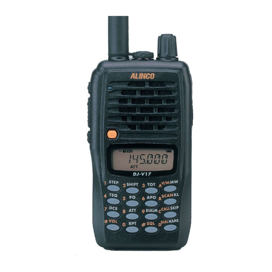
VHF FM TRANSCEIVER DJ-V17T/E/R/TFH Instruction Manual Thank you for purchasing your new Alinco transceiver. This instruction manual contains important safety and operating instructions. Please read this manual carefully before using the product and keep it for future reference. ALINCO, INC. - Page 2 FOR HOME OR OFFICE USE Information in this document is subject to change without notice or obligation. All brand names and trademarks are the property of their respective owners. Alinco cannot be liable for pictorial or typographical inaccuracies. Some parts, options and/or accessories are unavailable in certain areas.
-
Page 3: Notice / Compliance Information Statement
Copyright © All rights reserved. No part of this document may be reproduced, copied, translated or transcribed in any form or by any means without the prior written permission of Alinco. Inc., Osaka, Japan, English Edition Printed in Japan. - Page 4 Warning Warning To prevent any hazard during operation of Alinco's radio product, in this manual and on the product you may find symbols shown below. Please read and understand the meanings of these symbols before starting to use the product.
-
Page 5: Warning
Warning Do not use multiple radios in very close proximity. It may cause interference and/or damage to the product(s). Risk of explosion if battery is replaced with an incorrect type. Dispose of, or recycle used batteries according to your local regulations. The manufacturer declines any responsibilities against loss of life and property due to a failure of this product when used with or as a part of a device made by third parties. - Page 6 Warning Do not handle a power supply with a wet hand. It may result in electric shock. Securely plug the power supply to the wall outlet. Insecure installation may result in short-circuiting, electronic shock and/or fire. Do not plug the power supply into the wall socket if the contacts are dirty. Short-circuit and/or overheating may result in fire, electric shock and/or damage to the product.
- Page 7 Warning Caution Environment and condition of use Do not use the product in proximity to a TV or a radio. It may cause interference or receive interference. Do not install in a humid, dusty or insufficiently ventilated place. It may result in electric shock, fire and/or malfunction.
-
Page 9: Introduction
Introduction Introduction Thank you very much for purchasing this excellent Alinco transceiver. Our products are ranked among the finest in the world. This radio has been manufactured with state of the art technology and it has been tested carefully at our factory. It is designed to operate to your satisfaction for many years under normal use. -
Page 10: Table Of Contents
Contents Contents NOTICE / Compliance Information Statement ..........3 Warning.......................5 Introduction ......................9 Contents ......................10 1.Features ......................13 Accessories ......................13 2.Accessories ....................14 Installations ......................14 2.1.1 Antenna ......................14 2.1.2 Hand Strap....................14 2.1.3 Belt Clip .....................14 2.1.4 Battery Pack ....................15 2.1.5 Prevent Short Circuiting the Battery Pack ..........17 2.1.6 Dry Cell Case (optional)................18 2.1.7... - Page 11 Contents Receiving ......................29 4.7.1 Monitor Function..................29 Transmitting .......................30 4.8.1 Selecting the Output Level .................30 5.Useful Functions ...................31 Scan Modes......................31 5.1.1 VFO-Scan....................31 5.1.2 Memory-Scan .....................31 5.1.3 Setting Skip Channels ................32 Keylock .......................32 Tone-Burst ......................32 Naming Memory Channels .................33 5.4.1 Setting Name-Tag..................33 5.4.2 Using the Channel Name Function ............33 Auto-Power-Off (APO) ..................34...
- Page 12 Contents 7.Special Functions..................42 ATT (Attenuator) ....................42 Battery Refresh ....................42 Repeater-Access....................43 8.Set Mode......................44 Set Mode Operation ....................44 Entering the Set Mode ..................44 Available Parameters ..................45 8.3.1 Menu 1 Battery Save (BS) Function ............45 8.3.2 Menu 2 Timer/Busy Scan Setting ..............45 8.3.3 Menu 3 Beep Function ................45 8.3.4 Menu 4 Tone-Burst Frequency Setting ............45...
-
Page 13: Features
1.Features 1. Features This transceiver has the following main features. High-grade waterproof compatible to IPX7 * (submersible 1m/3feet for 30min.) and rugged body 39 CTCSS tone squelch 104 DCS digital code squelch Time-Out-Timer Alphanumeric display 4 tone-burst tones (1750, 2100, 1000, 1450Hz) 9 auto dial memories easily accessed from the DTMF keypad with redial function Direct frequency entry from the DTMF keypad... -
Page 14: Accessories
2.Accessories 2. Accessories Installations 2.1.1 Antenna Attaching the Antenna 1. Hold the antenna by its base. 2. Align the grooves at the base of the antenna with the protrusions on the antenna connector. 3. Slide the antenna down and turn it clockwise until it stops. -
Page 15: Battery Pack
2.Accessories 2.1.4 Battery Pack For the specifications and the charging procedures, please refer to "Battery Packs"(page 56) and "Using the Chargers"(page 57). Attaching the Battery Pack Align the catches on the battery pack with the Catch grooves on the unit, and close the latch until it clicks. Latch Groove Removing the Battery Pack... - Page 16 2.Accessories Caution • Li-ion battery packs can't be charged using DC-jack on the unit (Only Ni- MH battery packs can be charged). • Risk of explosion, generation of heat or leak of chemicals inside if the battery is replaced by an incorrect type. Use always the recommended types of batteries in this manual only.
-
Page 17: Prevent Short Circuiting The Battery Pack
2.Accessories NOTE: • Please read the general safety instructions included in the optional accessories to correctly and safely use them. • EDC-146/147/148 can't be used as the adapter for operation. These adapters are for charging purposes only. • Chargers can't perform the correct charge when the AC voltage is unstable. •... -
Page 18: Dry Cell Case (Optional)
2.Accessories 2.1.6 Dry Cell Case (optional) An EDH-34 is available for operation with using AA cells. Lift up the catches on the top of the case to remove the cover. Place 6 AA cells, then close the cover in order of then . -
Page 19: Names And Operations Of Parts
3.Names and Operations of Parts 3. Names and Operations of Parts Names and Operations of Keys and Ports Top and Front Dial Rotate the dial to select the frequency of operation, memory channel, offset frequency, tone frequency, DCS code, Set mode settings, and the characters for name-tags. - Page 20 3.Names and Operations of Parts Side Antenna side Dial side SMA Antenna Attach the whip antenna. If you plan to use an optional antenna, Connector select one that is tuned to the operating frequency. FUNC key The FUNC key is used in combination with the other keys to access the various functions of the unit.
-
Page 21: Keypad
3.Names and Operations of Parts Keypad Without pressing the FUNC key. While appears after the FUNC key is pressed. Inputs* 1. Channel step setting (page 25). Inputs 2. Offset frequency setting (page 26). Inputs 3. Time-Out-Timer setting (page 35). Inputs 4. Tone Encode / Tone Squelch setting (page 36). -
Page 22: Display (Lcd)
3.Names and Operations of Parts Display (LCD) Appears when the FUNC key is pressed. Indicates the shift (+/-) direction. Appears when setting the CTCSS tone encoder. Appears when setting the tone squelch. Appears when setting the DCS. Displays the frequency and scan operation. Displayed when the frequency or the keypad is locked. -
Page 23: Basic Operation
4.Basic Operation 4. Basic Operation Turning On the Power Hold the key down for a second. To turn off the power, hold the key down until the display turns off. Adjusting the Audio Output (Volume) • There are 21 audio output levels (00~20). •... -
Page 24: Setting The Frequency In The Vfo Mode
4.Basic Operation Setting the Frequency in the VFO Mode The factory default of this unit is the VFO mode. The VFO mode allows you to change the frequency and operating parameters by using the dial and key operations. 4.4.1 Setting the Frequency To Select the VFO Mode key switches between the VFO and Memory mode each time the key is pressed. -
Page 25: Setting The Tuning Step
4.Basic Operation Tuning step Entry completion digit Final digit selection 5.0kHz 1kHz Accept 0 or 5 as valid number. 10.0kHz 10kHz Accept any of 0 to 9 keys. 12.5kHz 10kHz When you input the 10kHz digit, the 1kHz digit is set automatically as follows. -
Page 26: Shift Direction And Offset Frequency Settings
4.Basic Operation 4.4.3 Shift Direction and Offset Frequency Settings In conventional repeater systems, a signal received on one frequency is retransmitted on another frequency. The difference between these two frequencies is called the offset frequency. The selectable offset frequency of this unit is from 0 to 99.995MHz. 1. -
Page 27: Recalling A Memory Channel
4.Basic Operation 5. Pressing the FUNC then key while is displayed on the programmed channel will delete the memory data and it becomes available for reprogramming. 4.5.2 Recalling a Memory Channel 1. Select the Memory mode by pressing the key. " "... -
Page 28: Programmable Parameters In Memory Channels
4.Basic Operation 4.5.5 Programmable Parameters in Memory Channels The following parameters can be stored in each of the memory channels. • Frequency • Offset frequency * • Shift direction (+/-) * • Tone encoder frequency * • Tone decoder frequency * •... -
Page 29: Receiving
4.Basic Operation IMPORTANT NOTE: • The dial and direct key-entry of frequency/memory channel are blocked in the Call mode. • It is possible to temporary change the offset and CTCSS/DCS related parameters in the Call mode. • The Scan function is deactivated in the Call mode. •... -
Page 30: Transmitting
4.Basic Operation Transmitting 1. Select the frequency that you wish by using the dial or keypad. 2. Press the PTT key. The red TX indicator turns on while transmitting. 3. While holding down the PTT key, speak into the unit at normal voice from the distance of 5cm (2"). -
Page 31: Useful Functions
5.Useful Functions 5. Useful Functions Scan Modes The scan function automatically searches the receiving signals. There are 2 modes for scan-resume condition. • Busy Scan: The scan stops when a signal is detected, stays until the signal is gone then resumes scanning. •... -
Page 32: Setting Skip Channels
5.Useful Functions 5.1.3 Setting Skip Channels You can select the memory channels that you wish to skip during the memory-scan. • Press the FUNC key in the Memory mode, and while is displayed, press the key to set the currently selected memory channel as a skip channel. Use the same procedure to clear the skip channel setting. -
Page 33: Naming Memory Channels
5.Useful Functions Naming Memory Channels In the Memory mode, it is possible to display up to 7 alphanumeric characters (Name- tag) instead of conventional frequency display. 5.4.1 Setting Name-Tag 1. Select the memory channel. 2. Press the FUNC key, and while is displayed press the key. -
Page 34: Auto-Power-Off (Apo)
5.Useful Functions Auto-Power-Off (APO) This function prevents an useless battery consumption. 5.5.1 Setting APO Press the FUNC key, and while is displayed on the LCD, press the key. displayed on the LCD, and the Auto-Power-Off function is set. Repeat the same to turn it off. -
Page 35: Time-Out-Timer (Tot)
5.Useful Functions Time-Out-Timer (TOT) This function automatically stops transmission when a preset time is elapsed. 5.6.1 Setting TOT 1. Press the FUNC key, and while is displayed on the LCD, press the key. T- OFF is displayed on the LCD. 2. -
Page 36: Selective Calling
6.Selective Calling 6. Selective Calling Selective Calling Operations • To communicate only with selected stations, use either the Tone Squelch or the DCS function. The Tone Squelch function unmutes the squelch only when a signal added with one of the matching 39 CTCSS tone frequencies is received. •... -
Page 37: Switching Off The Tone Squelch
6.Selective Calling 6.1.2 Switching Off the Tone Squelch Press the key in Tone Squelch Setting mode to select TCS-OF, then press any key other than the MONI key to complete the setting. 6.1.3 To Differentiate the ENC/EDC Tones It is possible to set the encode and decode tones independently in the Tone Squelch Setting mode. -
Page 38: Changing The Dcs Code
6.Selective Calling 6.2.2 Changing the DCS Code 1. Rotate the dial in DCS Code Setting mode (while " " is displayed). 2. Press any key other than the MONI key to complete the setting. • The same DCS code is set for ENC/DEC, differential setting isn't available. One of the following 104 DCS codes can be selected. -
Page 39: Dtmf Tone Encoding
6.Selective Calling Advantage of DET It enables DCS squelch operation even in poorer signal conditions. Disadvantage of DET When it is activated, suppose 2 stations are sharing the same channel and using the DCS selective-calling technique and transmitting at the same time. After station A with its corresponding DCS is gone, you may still hear station B even his DCS code is different from A, although he can't open your DCS squelch by his signal alone. -
Page 40: Auto Dialer
6.Selective Calling Auto Dialer The DTMF tones can be stored in the memory to automatically transmit. 6.4.1 Setting the Auto Dialer • All 16 DTMF tones up to 16 characters are available for each of 9 memories called an Auto Dialer memory. Programming the Auto Dialer Memories 1. -
Page 41: Redial
6.Selective Calling 6.4.3 Redial This function generates the last DTMF tones used by the unit. 1. Press the key while the unit is receiving. 2. Press the key. The last DTMF tones (either the auto dialer code or a manually input DTMF code) is automatically generated from the speaker. The unit doesn't transmit the tones in this operation. -
Page 42: Special Functions
7.Special Functions 7. Special Functions ATT (Attenuator) Use this function when the receiving signal is interfered by strong signals of nearby channels. When you activate this function, the transceiver attenuates the receiving sensitivity. 1. Press the FUNC key, and while is displayed on the LCD, press the key. -
Page 43: Repeater-Access
7.Special Functions Caution • The time to refresh totally depends on the remaining charge of the battery pack. To discharge the fully-charged EBP-65 may take up to approx. 7 hours. • When this function is on, the backlight and the keys are illuminated, and noise from the speaker can be heard. -
Page 44: Set Mode
8.Set Mode 8. Set Mode The Set mode is used to customize the various operational parameters of your DJ-V17. Set Mode Operation This chart shows the available parameters in the Set mode. enu Default setting Function BS-ON Battery Save ON/OFF TIMER Timer/Busy scan setting MONI key... -
Page 45: Available Parameters
8.Set Mode Available Parameters 8.3.1 Menu 1 Battery Save (BS) Function This function prevents useless battery consumption by switching the power ON/OFF at a fixed ratio if there is no key operation or receiving signal for a continuous period of 5 seconds or more. 1. -
Page 46: Menu 5 Clock Shift Setting
8.Set Mode 8.3.5 Menu 5 Clock Shift Setting In the unlikely event that you may hear a weak noise always on the same frequency, it may be so-called a CPU-clock noise. Unfortunately this is due to the circuit-design of this product and can't be eliminated, but can be moved away to another frequency. 1. -
Page 47: Menu 7 Tot Penalty Time
8.Set Mode 8.3.7 Menu 7 TOT Penalty Time This parameter determines the time to resume the transmission after the unit is forced to quit transmitting by TOT. 1. TP-OFF is displayed on the LCD. 2. Rotate the dial to change the TOT Penalty Time setting. TP-OFF TP-1 -----... -
Page 48: Menu 10 Dtmf First Digit Burst Time
8.Set Mode 8.3.10 Menu 10 DTMF First Digit Burst Time It often happens that the radios fail to receive the very beginning instant of each communication due to squelch/TSQ/DCS etc. By setting the burst time of the first digit longer, the risk to miss the first DTMF tone will decrease. 1. -
Page 49: Menu 12 Battery Type Setting
8.Set Mode 8.3.12 Menu 12 Battery Type Setting Select the correct battery type from Ni-MH battery pack, Li-ion battery pack and Alkaline dry cells in order to display the battery-level icon correctly and to perform the battery-charge using the DC-jack. 1. -
Page 50: Cloning And Packet Operation
9.Cloning and Packet Operation 9. Cloning and Packet Operation Cloning The memory data and customized operational parameters can be transferred from a Master unit to other DJ-V17 (Slave units). 9.1.1 Cable Connection • Make sure that both units are turned off before connecting the cable. •... -
Page 51: Master Unit Operation
9.Cloning and Packet Operation 9.1.3 Master Unit Operation 1. In the Clone mode, press the PTT key of the master unit. "SD***" is displayed on the LCD, and starts the data-transfer. 2. After the transfer is completed successfully, "PASS" is displayed. 3. -
Page 52: Packet Operation
9.Cloning and Packet Operation Packet Operation Packet operation is one of the data communication methods, which enables data transmission and reception with a personal computer through an optional TNC unit. 9.2.1 Packet Operation Connections Connect an optional EDS-10 Microphone/Speaker cable plug to the MIC/SP jack on the top of the unit, and connect the TNC (Terminal Node Controller) to the SP jack with 3.5Ø... -
Page 53: Maintenance And Reference
* Please be advised that the water-proof shields including jack caps are subject to consume. The factory warranty for IPX7-grade water-proof is 1 year. Please consult with your local dealer when further service-assistance may be necessary. Please visit alinco.com's "DISTRIBUTION" menu to locate the nearest dealer. -
Page 54: Resetting
2. All the icons appear on the display. Release the keys. All display will disappear for 2 seconds, and then reappear. The initial mode is the VFO. Factory default settings DJ-V17T DJ-V17E DJ-V17TFH/R VFO Frequency 145.000MHz 145.000MHz 155.000MHz CALL Frequency 145.000MHz... -
Page 55: Options
10.Maintenance and Reference 10.3 Options EBP-63 Li-ion Battery Pack (DC 7.4V 1100mAh) EBP-64 Li-ion Battery Pack (DC 7.4V 1600mAh) EBP-65 Ni-MH Battery Pack (DC 7.2V 700mAh) EBP-66 Ni-MH Battery Pack (DC 7.2V 2000mAh) EDC-36 Mobile Cigarette Lighter Adapter with Active Noise Filter EDC-37 External DC Power Supply Cable EDC-43... -
Page 56: Microphone/Speaker Cable (Eds-10)
10.Maintenance and Reference • Please purchase an optional EDS-10 cable to operate optional accessories marked *. • When using EDC-36, EDC-37, EDC-43, EDC-146, EDC-147, EDC-148, connect them to the unit first before turning on the unit. • EBP-63, 64, 65 and 66 are IPX7-grade water-proof only when correctly attached and used with DJ-V17. -
Page 57: Using The Chargers
10.Maintenance and Reference 10.3.3 Using the Chargers Caution Please also read the "Warning" (page 5 of this manual) and the safety instruction that is included in the accessories' package before operating with them for your safety. Charging with the EDC-143 (Trickle Charger) Please make sure that following items are included in the package. - Page 58 10.Maintenance and Reference 3. Press the sides of the adjustment plate, and attach Adjustment it to the proper grooves of the basket according to plate the size of the battery pack. Please be sure to place the plate all the way down to the bottom. Groove Adjustment plate...
- Page 59 10.Maintenance and Reference Charging with the EDC-144 (Quick Charger) Please make sure that following items are included in the package • EDC-144A: EDC-144 basket, EDC-150 adapter (AC 120V), insulation sheet • EDC-144E: EDC-144 basket, EDC-151 adapter (AC 240V), insulation sheet •...
- Page 60 5. The red indicator turns off when the charge is completed. Remove the battery pack from the basket. NOTE: The flashing red indicator means that the charger isn't working properly. Stop using it immediately, remove the cord form the outlet and consult with your local Alinco dealer. Specifications EBP-63 EBP-64 EBP-65...
- Page 61 10.Maintenance and Reference Connecting Additional Baskets (EDC-143R/144R) In order to use EDC-143R and EDC-144R, an optional power supply (IEC/EN 60950 compliant) of 1A/5A minimum respectively is required. A DC cable isn't included in the package; the suggested DC cable is 20 AWG wire, shorter than 1m (3feet) in length.
- Page 62 10.Maintenance and Reference 5. Connect the other ends of the DC cable to the output terminals of the power supply. Power supply Be mindful to the polarities of the terminals. DC cable...
-
Page 63: Specifications
11.Specifications 11. Specifications General Frequency range TX144~147.995MHz * 144~147.995MHz RX130~173.995MHz * 144~147.995MHz TX144~145.995MHz * 144~145.995MHz RX144~145.995MHz * 144~145.995MHz TFH/R:TX130~173.995MHz * 150~173.995MHz RX130~173.995MHz * 150~173.995MHz * Guaranteed range Modulation: F3E (FM) Frequency step: 5, 10, 12.5, 15, 20, 25, 30kHz step Memory channel: 200 channels + 1 call channel + 1 Repeater-Access function memory... - Page 64 11.Specifications Transmitter Power output: Approx. 5W (with EBP-65N) Approx. 5W (with DC 13.8V) Approx. 0.8W (LOW output) Modulation: Variable reactance Spurious emission: -60dB or less Max. deviation: ±5kHz Mic. impedance: 2k Ω Receiver System: Double-conversion super heterodyne Sensitivity: -14.0dBµ (0.2µV) or less Intermediate frequency: 1st IF 21.7MHz 2nd IF 450kHz...
- Page 65 ALINCO, INC. Head Office:Shin-Dai building 9th Floor 2-6, 1-Chome, Dojimahama, Kita-ku, Osaka 530-0004, JAPAN Phone:+81-6-4797-2136 Fax: +81-6-4797-2157 E-mail:export@alinco.co.jp Printed in Japan Copyright Alinco, Inc. PS0520A/FNNJ...
Need help?
Do you have a question about the DJ-V17TFH and is the answer not in the manual?
Questions and answers