Table of Contents
Advertisement
ALINCO, INC.
Yodoyabashi Dai-bldg 13F
4-4-9 Koraibashi, Chuo-ku, Osaka 541-0043 Japan
Phone: +81-6-7636-2362 Fax: +81-6-6208-3802
http://www.alinco.com
E-mail:export@alinco.co.jp
VHF FM Transceiver / 136.000-173.995MHz
All EU and EFTA member states. Operator
license is required.
Copyright Alinco, lnc. PS0662/FNEF-NJ
Printed in China
Advertisement
Table of Contents

Related Manuals for Alinco DJ-A10


Summary of Contents for Alinco DJ-A10
- Page 1 ALINCO, INC. Yodoyabashi Dai-bldg 13F 4-4-9 Koraibashi, Chuo-ku, Osaka 541-0043 Japan Phone: +81-6-7636-2362 Fax: +81-6-6208-3802 http://www.alinco.com E-mail:export@alinco.co.jp VHF FM Transceiver / 136.000-173.995MHz All EU and EFTA member states. Operator license is required. Copyright Alinco, lnc. PS0662/FNEF-NJ Printed in China...
-
Page 2: Instruction Manual
VHF FM Transceiver Instruction Manual Thank you for purchasing your new Alinco transceiver. Please read this manual carefully before using the product to ensure full performance, and keep this manual for future reference as it contains information on after-sales service. -
Page 4: Before Transmitting
Introduction Thank you very much for purchasing this excellent Alinco transceiver. Our products are ranked among the finest in the world. This radio has been manufactured with state of the art technology and it has been tested carefully at our factory. It is designed to operate to your satisfaction for many years under normal use. - Page 5 Alinco accessories and the radio has not been disassembled by the customer. The factory has tested and made the equipment compatible to IP54 certification during engineering.
- Page 6 Features ■ Output power selectable 5W/2W/0.5W ■ 128 PC-programmable channels ■ Li-Ion battery pack and stand-charger as standard accessories ■ Alphanumeric name tags ■ FM broadcasting 76-108MHz receiver built-in ■ Selectable Battery-save parameters ■ Busy Channel Lockout ■ Voice Compander (Reduce Noise & enhance audio clarity) ■...
-
Page 7: Safety Training Information
DO NOT operate the transceiver without a proper antenna attached, as it may damage the transceiver and may also cause you to exceed FCC RF exposure limits. A proper antenna is the genuine antenna supplied with this transceiver by Alinco or ones specifically authorized by the antenna manufacturer for use with this transceiver. - Page 8 • Use only the genuine Alinco accessories listed in this instruction manual for RF safety. Third party accessories are not guaranteed for RF safety by Alinco. The above provides the information needed to make users of this transceiver aware of RF exposure, and what to do to assure that this transceiver operates with the FCC RF exposure limits.
-
Page 9: Fcc Information
FCC INFORMATION FOR CLASS B UNINTENTIONAL RADIATORS: This equipment has been tested and found to comply with the limits for a Class B digital device, pursuant to part 15 of the FCC Rules. These limits are designed to provide reasonable protection against harmful interference in a residential installation. -
Page 10: Environment And Condition Of Use
Alert Environment and condition of use It is recommended that you check local traffic regulations regarding the use of a radio equipment while driving. Some countries prohibit or apply restrictions for the operation of radios and mobile- phones while driving. Do not use this product in close proximity to other electronic devices, especially medical ones. -
Page 11: Handling This Product
The manufacturer declines any responsibilities against loss of life and property due to a failure of this product when used with or as a part of a device made by third parties. Use of third party accessory may result in damage to this product. It will void our warranty for repair. Handling this product Be sure to reduce the audio output level to minimum before using an earphone or a headset. -
Page 12: In Case Of Emergency
Securely plug the adapter into the wall outlet. Insecure installation may result in short-circuit, electronic shock and/or fire. Do not use the adapter if the plug or socket contacts are dirty. Overheating and/or short-circuiting may result in fire, electric shock and/or damage to the product. In case of emergency In case of the following situation(s), please turn off the product, switch off the source of power, then remove or unplug the power-cord. -
Page 13: About Transceiver
Alert Environment and condition of use Do not use the product in proximity to a TV or a radio. It may cause interference or receive interference. Do not install in a humid, dusty or insufficiently ventilated place. It may result in electric shock, fire and/or malfunction. - Page 14 Use a clean, dry cloth to wipe off dirt and condensation from the surface of the product. Never use thinner or benzene for cleaning. Check with your local waste officials for details on recycling or proper disposal in your area. PC PROGRAMMING NOTE: The utility software may be available to distributors/dealers only.
-
Page 15: Table Of Contents
TABLE OF CONTENTS STANDARD ACCESSORIES ............................01 Standard Accessories ..............................01 OPERATION MODE (VFO mode and Channel mode) ....................02 KEY OPERATIONS / QUICK CHART ...........................04 BATTERY INFORMATION .............................11 Charging Operation ..............................11 Battery Charger Type ..............................11 Notice for Charging Battery ............................11 How to Charge the battery pack ..........................13 INSTALLATION &... - Page 16 TABLE OF CONTENTS Channel Input by Keypad ............................23 Adjusting Channel / Frequency By " 【 B 】 " Key & " 【 C 】 " Key ................24 Alarm ..................................24 Monitor / Squelch Off ..............................24 Receiving ...................................25 Transmitting................................25 Side Key 【 PF1 】 Function Instruction ........................25 Side Key 【...
- Page 17 TABLE OF CONTENTS Tone Squelch / DCS squelch (Sub tone CTCSS / DCS ) Encode Tone Setup ............36 Tone Squelch / DCS squelch (Sub tone CTCSS / DCS)Encode/Decode tones synchronized setup ......37 Offset Frequency ................................38 Wide/ Narrow Channel-spacing Selection ........................38 Frequency Reverse or Talk Around ..........................39 Inversion scrambling (Encryption) ..........................39 Voice Compander (Reduce noise &...
- Page 18 TABLE OF CONTENTS Tone Burst Tone ................................51 DTMF Transmitting Time ............................52 Beep Volume level ..............................52 Priority Channel Setup ...............................53 Current Battery Voltage Display ..........................53 Resume Factory Default (RESET) ..........................54 DEFAULT SETTINGS ..............................55 OPTIONAL ACCESSORIES ............................56 RECOMMENDED INSTALLATION OF EARPHONE MICROPHONE................57 TECHNICAL SPECIFICATIONS ............................58 TROUBLE SHOOTING GUIDE ............................60 ATTACHED CHART ...............................62...
-
Page 19: Standard Accessories
STANDARD ACCESSORIES Standard Accessories Antenna Battery Charger AC Adaptor Belt Clip Instruction Hand Strap Manual NOTE: Accessories may differ depending on the version you have purchased. Please contact your local dealer for details of standard accessories and the warranty-policy before purchase. Professional FM Transceiver... -
Page 20: Operation Mode (Vfo Mode And Channel Mode)
OPERATION MODE (VFO mode and Channel mode) You may set the radio as VFO mode and Channel mode. There are also different setting parameters to properly set functions as per your operating comfort. 1. By programming software: In PC programming utility software, "General Setting" menu, choose "Display Mode" to select VFO mode or Channel mode. - Page 21 OPERATION MODE (VFO mode and Channel mode) 3.Commercial radio Mode: When set display mode as "CH", it enters into Commercial radio mode. At this mode, except scanning, talk around/frequency reverse, DTMF encode or editing, BEEP on/off and keypad lock, all other functions should be set by PC software (Pic 4) in advance to the operation (As pic 4).
-
Page 22: Key Operations / Quick Chart
KEY OPERATIONS / QUICK CHART Function Key Operation Parameter Instruction Page 【 1 】 【 A 】 FM Radio On/Off Activate FM broadcasting receiver 【 A 】 【 2 】 Beep Setup Beep sound ON/OFF 【 A 】 【 3 】 CTCSS/DCS Scan CTCSS Scan 【... - Page 23 KEY OPERATIONS / QUICK CHART Function Key Operation Function Option Display 【 A 】 【 8 】 【 B 】 【 C 】 Sub tone (CTCSS / DCS) Decode Setup Sub tone (CTCSS / DCS) Encode Setup 【 A 】 【...
-
Page 24: Key Operation
KEY OPERATIONS / QUICK CHART Key Operation Parameter Instruction Enter and exit Page Sub-tone setting: Operations are common to Decode (R-CDC), Encode (T-CDC) and Synchronous (C-CDC). Press CTCSS (50 Groups in total): 67Hz-254.1Hz 【 D 】 【 # 】 【 A 】 Key to move cursor to the menu, Press 【 1 】 DCS (232Groups in total): 017N-765I Key to choose CTCSS/DCS/OFF, Press 【... - Page 25 KEY OPERATIONS / QUICK CHART Key Operation Parameter Instruction Enter and exit Page OFF: Disable Busy-Channel-Lockout (BCL): BCL: Prohibit transmitting when receiving a carrier 【 D 】 【 # 】 Press【A】Key to move cursor to the menu, Press and squelch is open. 【B】/【C】Key to choose the value.
- Page 26 KEY OPERATIONS / QUICK CHART Function Menu Entry Function Option Display 【 B 】 【 C 】 Voice Prompting Selection Press PF2 and hold this key for 3 seconds 【 B 】 【 C 】 Time-Out Timer (TOT) Press PF2 and hold this key for 3 seconds 【...
- Page 27 KEY OPERATIONS / QUICK CHART Parameter Adjustment Parameter Instruction Confirm to back Page Voice prompt: Press 【 A 】 Key to move cursor to the menu 【 D 】 【 # 】 ENG: Activate English Voice-guide Press 【 B 】 / 【 C 】 key to choose the value OFF: OFF Time-out-timer setting: Press 【...
- Page 28 KEY OPERATIONS / QUICK CHART LCD backlight color selection: Press 【 A 】 Key to move cursor to the menu BLUE: Blue backlight 【 D 】 【 # 】 Press 【 B 】 / 【 C 】 key to choose the value ORG: Orange backlight PUR: Purple backlight Press 【...
-
Page 29: Battery Information
Battery Charger Type Please use Alinco's designated charger, other models may cause explosion and injure people. After installing the battery, when the radio displays low battery, please charge the battery. - Page 30 BATTERY INFORMATION ▲Do not charge the battery or transceiver when wet. Dry it before charging to avoid danger. Caution • Risk of explosion, generation of heat or leak of chemicals inside if the battery is replaced by an incorrect type or reverse polarity. Use always the recommended types of batteries in this manual only. •...
-
Page 31: How To Charge The Battery Pack
BATTERY INFORMATION How to Charge the battery pack 1.Plug the AC adaptor into the AC outlet, then plug into the DC jack ,the indicator lights orange for 1 second and goes out---waits to charge. 2.Slide the battery or transceiver with battery into the charger;... - Page 32 BATTERY INFORMATION 6. LED Indicator: self-examine Charge Fully STATUS (No battery) Pre-charging Trouble when power on normally Charged Orange Red light twinkles Red twinkles None Green (for 1 second) for 5 minutes alternatively NOTE: ▲ Trouble means battery heating, short-circuit or charger malfunction. Remove the battery pack from the charger immediately and contact to your local dealer for services.
-
Page 33: Installation & Connection
INSTALLATION & CONNECTION How to Store the Battery WARNING Do notshort-circuit battery terminals. 1.The battery should be kept in the status Never attempt to remove the casing from the battery of 50% discharge when storing. pack. 2.It should be kept in cool, dry environment Never assemble the battery hazardous in explosive and remove it from the transceiver. -
Page 34: Installing / Removing The Antenna
INSTALLATION & CONNECTION Installing / Removing the Antenna Installing the Antenna: 1. Hold the antenna by its base. 2. Align the grooves at the base of the antenna with the protrusions on the antenna connector. 3. Slide the antenna down and turn it clockwise until it stops. 4. -
Page 35: Accessories
INSTALLATION & CONNECTION Accessories Open the jack cover and insert the accessory plug into the jack,as shown. When the accessory is not used, please be sure to close the cover securely. NOTE: 1.To keep the radio dust and splash resistant, the cover must be closed properly with the original supplied cover. -
Page 36: Getting Acquainted
GETTING ACQUAINTED LCD Display Following are the meaning of the icons and signs shown on the display. Some icons may not appear while operating this product due to pre-programming status by your dealer. Frequency Reverse Priority Scan VOX Function Offset direction Scan Skip Talk Around Narrow band... -
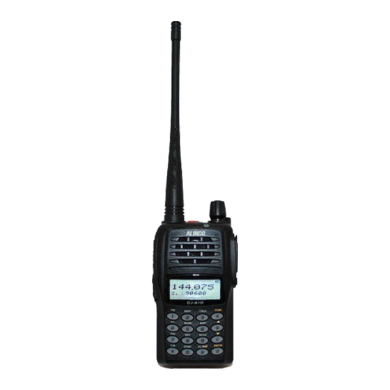
Page 37: Front Panel
GETTING ACQUAINTED Front Panel Jacklight Antenna Power / Volume Switch Emergency Alarm LED Indicator, green light when transmitting, red light when receiving Speaker Microphone A key/Function key B key / Up key Numeric keys C key / Down key D key, Exit key or channel/VFO Exchange key Professional... -
Page 38: Side Panel
GETTING ACQUAINTED Side Panel PTT key Accessory and PC programming port PF1 key (1 Primary Function key) PF2 key (2 Primary Function key) Belt Clip Battery Left Panel Right Panel Professional FM Transceiver... -
Page 39: Basic Operations
BASIC OPERATIONS Power On and off Turn 【 POWER 】 / 【 VOLUME 】 dial clockwise to power on. Turn it counterclockwise to power off. Adjusting Audio output level Press and hold PF2 key to monitor white noise to refer to the current audio level. -
Page 40: Emergency Alarm Function
BASIC OPERATIONS Emergency Alarm Function While Stand-by state, press this key for 3 seconds to enable the emergency alarm function. When activated the function, the radio will sound an alarm beep and start transmitting the alarm beep. The alarming lasts 1 minute, then the radio will return to Stand-by, or you may press this key again to stop alarming. -
Page 41: Frequency Input By Keypad
BASIC OPERATIONS Frequency Input by Keypad In VFO mode or FM radio receiver, You may directly enter frequency through numeric keys. 1.Press 【 D 】 to switch to VFO. 2.Enter the desired frequency in 6-digit by numeric keys. Example: To enter 155.125, press [1][5][5][1][2][5].By pressing the last [5], a dot appears after the MHz unit and the radio is ready to operate. -
Page 42: Adjusting Channel / Frequency By " " Key & " " Key
BASIC OPERATIONS Adjusting Channel / Frequency By " " Key & " " Key 【 B 】 【 C 】 In VFO mode, you may use 【 B 】 key/ 【 C 】 key as up/down keys to change the operating frequency. Press 【... -
Page 43: Receiving
BASIC OPERATIONS Receiving Select the operating mode and frequency or channel that you wish to operate. When a signal is received on the frequency that you selected, and S-meter is displayed on the LCD, then the received signal can be heard. The RX indicator also lights green at this time. NOTE: Please be aware of the squelch level and selective-calling settings such as CTCSS and DCS as you may risk not hearing the receiving signal. -
Page 44: Side Key 【 Pf2 】 Function Instruction
BASIC OPERATIONS 3. Alarm Off: In the alarm mode, press this key to stop the alarm. 4. Jacklight Switch: In stand-by, press this key to switch on or off the jacklight. 5. Tone-burst tone transmitting: While transmitting, press and hold this key to send the selected tone- burst tone. -
Page 45: Advanced Operations
ADVANCED OPERATIONS Editing Channels 1.In VFO mode, enter the frequency and set the operating parameters as you desire. After pressing 【 A 】 key, While icon is displayed on the top left corner, press and hold 【 D 】 key for 2 seconds. A beep sounds "DU" and LCD displays the channel No. -
Page 46: Enable /Disable Beeping
ADVANCED OPERATIONS Enable /Disable Beeping Beep sounds to confirm or alert the operation status. In Stand-by conditions, after pressing 【 A 】 key, While icon is displayed on the top left corner, press 【 2 】 key to turn off the beep. Repeat it to enable beep sounds. -
Page 47: Frequency/Channel Scan
ADVANCED OPERATIONS pressing 【 A 】 key, while icon is displayed on the top left corner, press 【 4 】 key to choose positive offset direction (+), minus offset direction (-) or exit setting (no icons displayed). 1.(+)Positive offset: Indicates the frequency is higher than receiving frequency. When enable reverse function, the receiving frequency is higher than transmitting frequency. -
Page 48: Channel Scan Skip
ADVANCED OPERATIONS NOTE: Frequency scan checks all bands allocated to the VFO. When channel scanning, the skipped channel is excluded from the scanning. While scanning, change the direction upward/downward by pressing 【 B 】 key or 【 C 】 key. When a signal is being received, the scan stops for 15 seconds and resume scanning. Channel Scan Skip In Channel+Name Tag mode or Frequency+Channel mode, after pressing 【... -
Page 49: Tx Power Selection
ADVANCED OPERATIONS TX Power Selection After pressing 【 A 】 key, while icon is displayed on the top left corner, press 【 9 】 key to set the output power. When the bottom left corner of screen displays 'H' the power is 5W/high power.‘L’ for 0.5W. When nothing is displayed, the output power is middle/2W. - Page 50 ADVANCED OPERATIONS characters using corresponding keys. Method 2: Press and hold 【 PTT 】 key to enter the first DTMF character, then release 【 PTT 】 key. It will remain transmitting for 2 seconds. You can keep entering the desired DTMF characters using keypad and don't need to always press and hold 【 PTT 】 key while operating.
-
Page 51: Remotely Kill / Waken
ADVANCED OPERATIONS For example: Group code as“C” (Radio A) (Radio B) (Radio C) (Radio D) Receiver self ID Caller press and hold PTT to input 123 223 235 or 355, A or B or C or D will receive selective calling. Caller press and hold PTT to input C23 , A and B will receive group calling. -
Page 52: Frequency Reverse / Talk Around On/Off
ADVANCED OPERATIONS NOTE: Remotely kill/stun codes should be preprogrammed using the programming software. The maximum available digit for the kill/stun codes is16. When awaken, radios return to normal operation Frequency Reverse / Talk Around ON/OFF After pressing 【 A】key, while icon is displayed on the top left corner, press 【... -
Page 53: Keypad Lock
ADVANCED OPERATIONS Keypad Lock Keypad lock function is useful to prevent from wrong operation, In stand-by state, after pressing【A 】 key, while icon is displayed on the top left corner, press and hold【# 】 key for 2 seconds to start keypad lock function. Repeat to cancel the key lock function. -
Page 54: Tone Squelch / Dcs Squelch (Sub Tone Ctcss / Dcs ) Decode Tone Setup
ADVANCED OPERATIONS Tone Squelch / DCS squelch (Sub tone CTCSS / DCS ) Decode Tone Setup This function enables the selective-calling and speaker sounds only when a signal with matching encoded CTCSS/DCS tone being received. 1. after pressing 【 A 】 key, while icon is displayed on the top left corner, press 【... -
Page 55: Tone Squelch / Dcs Squelch (Sub Tone Ctcss / Dcs)Encode/Decode Tones Synchronized Setup
ADVANCED OPERATIONS 4. Press 【 B 】 key or 【 C 】 key to choose the desired CTCSS / DCS encode tone. 5.Available CTCSS tones: 67Hz- 254.1Hz, 50 tones in total, Deafault is OFF. 6.DCS: 017N-765I, 232 codes, [N] stands for positive, [I] stands for inverse codes. Default is OFF Tone Squelch / DCS squelch (Sub tone CTCSS / DCS) Encode/Decode tones synchronized setup 1.after pressing 【... -
Page 56: Offset Frequency
ADVANCED OPERATIONS Offset Frequency In conventional repeater systems, a signal received on one frequency is retransmitted on another frequency. The difference between these two frequencies is called the offset frequency. The selectable offset frequency of this unit is from 0 to 70.00MHz. 1. -
Page 57: Frequency Reverse Or Talk Around
Inversion scrambling (Encryption) NOTE:This is an analog encryption and decoding is possible by using commonly available receivers. Alinco does not warranty the confidentiality of the communications. An analog voice inversion scrambler is equipped and such audio processing can offer an advanced confidentiality to your business communications. -
Page 58: Voice Compander (Reduce Noise & Enhance Audio Clarity)
ADVANCED OPERATIONS ON: Scramble is enabled. OFF: Scramble is disabled. Default setting is OFF. Voice Compander (Reduce noise & enhance audio clarity) Enabling this function to reduce background noise and enhance audio clarity. It is recommended to activate this function if all radios in your group are equipped with Voice Compander otherwise worse the clarity of communications. -
Page 59: Turn On/Off Optional Signaling Function
ADVANCED OPERATIONS function menu. 2.Press 【 B 】 / 【 C 】 key to choose Menu 9 and display “ BUSY ”. 3.Press 【 A 】 key then press 【 B 】 key or 【 C 】 key to choose the desired parameter. -
Page 60: Signaling Relations
ADVANCED OPERATIONS NOTE: DTMF signaling is applied as an optional signaling to this product. Signaling Relations Select how to operate the Selective-calling(Signaling) function. 1. after pressing 【 A 】 key, while icon is displayed on the top left corner, press 【... -
Page 61: Ptt Id
ADVANCED OPERATIONS PTT ID 1. after pressing 【 A 】 key, while icon is displayed on the top left corner, press 【 8 】 key to enter into function menu. 2.Press 【 B 】 / 【 C 】 key to choose Menu 12 and display “ PTT-ID ”. 3.Press 【... -
Page 62: Whisper
ADVANCED OPERATIONS Whisper This function is to increase your voice level while talking in low voice. Do not activate this function while you can talk normally otherwise the voice may be distorted. 1. after pressing 【 A 】 key, while icon is displayed on the top left corner, press 【... -
Page 63: Set Mode Operations
SET MODE OPERATIONS Set Mode Setting The Set mode is used to customize the various operational parameters of DJ-A10. The Set Mode parameters are stored and remain until next change regardless of power on/off operation. Set Mode Setting operation is as follows and common to all available menus: 1.Press and hold 【... -
Page 64: Time-Out-Timer(Tot)
SET MODE OPERATIONS Time-Out-Timer(TOT) This function stops the transmission automatically when the continuous transmission time exceeds the set time and alerts it with a beep. 1.Press and hold 【 PF2 】 key while turning on the radio, and keep pressing 【... -
Page 65: Vox Delay
SET MODE OPERATIONS VOX Delay This is to make a time delay at the end of VOX transmission. When you stop speaking to take breath, the radio still holds the transmission for the time you set in this menu. 1.Press and hold 【 PF2 】 key while turning on the radio, and keep pressing 【... -
Page 66: Frequency Step Size Setup
SET MODE OPERATIONS Frequency Step Size Setup Tuning step can't be changed in the Channel modes but usable only in VFO mode. Frequency input and frequency scan are both affected by tuning step setting. 1.Press and hold 【 PF2 】 key while turning on the radio, and keep pressing 【... -
Page 67: Battery Save
SET MODE OPERATIONS Battery Save This function prevents useless battery consumption by switching the power ON/OFF at a fixed ratio if there is no key operation or receiving signal for a continuous period of 5 seconds or more. Higher OFF time (1:4 setting) saves more amount of battery but may cause slight delay on receiving. -
Page 68: Lcd Backlight Color Setup
SET MODE OPERATIONS ON: Always lit, not recommended as it considerably consumes battery. OFF: Remain turned off always. LCD Backlight Color Setup There are three backlight colors available to suit your preference. 1.Press and hold 【 PF2 】 key while turning on the radio, and keep pressing 【... -
Page 69: Frequency/Channel Display Mode
SET MODE OPERATIONS 5ST: When receives signal, scan stops for 5 seconds and resume. 10ST: Same, 10 seconds. 15ST: Same, 15 seconds and default is 10s. Frequency/Channel Display Mode There are 3 different display modes available, Frequency + Channel mode, Channel mode and Channel+Name Tag modes. -
Page 70: Dtmf Transmitting Time
SET MODE OPERATIONS certain audible tone is required. DJ-A10 offers 4 major tones. 1.Press and hold 【 PF2 】 key while turning on the radio, and keep pressing 【 PF2 】 key for 3 seconds to enter into the Set Mode operations. -
Page 71: Priority Channel Setup
2.Press 【 B 】 / 【 C 】 key to choose the Menu 17 and display “ V-BATT ”. At this state, the approximate battery voltage is displayed on the LCD. Please note that the voltage is approximate and Alinco does not guarantee the accuracy. Professional... -
Page 72: Resume Factory Default (Reset)
SET MODE OPERATIONS Resume Factory Default (RESET) You can make all the settings of transceiver return to the factory default settings when it has troubles, can't work properly or simply you wish to change settings. 1.Press and hold 【 PF2 】 key while turning on the radio, and keep pressing 【... -
Page 73: Default Settings
DEFAULT SETTINGS VFO Frequency 155.000MHz FM Radio 1ch:155.000MHz Key Beep Memory Channel 2~128ch: Blank Offset Frequency Setup PF1 long press key Call Channel Scan Skip PF1 short press key Light Switch TX Power Selection High PF2 key Squelch Open Reverse / Talk Around Reverse Voice Prompting DTMF Code... -
Page 74: Optional Accessories
OPTIONAL ACCESSORIES EA-211 VHF & FM radio Antenna EBC-34 Belt Clip EBP-87 Li-ion Battery Pack (DC 7.4V 1500mAh) EBP-88 Li-ion Battery Pack (DC 7.4V 1700mAh) EDC-189 Li-ion Battery Charger EDC-190E AC Adaptor (220V Linear type) EDC-191E AC Adaptor (220V) EDC-191T AC Adaptor (120V) EME-56A Earphone Microphone... -
Page 75: Recommended Installation Of Earphone Microphone
RECOMMENDED INSTALLATION OF EARPHONE MICROPHONE Earphone Use a clip to fix with collar. Clip the PTT unit closer to your mouth. Carry the radio on the side or the back of your body, and the cable should go around the back as shown. Clamp the excessive length of cable at your waist Professional FM Transceiver... -
Page 76: Technical Specifications
TECHNICAL SPECIFICATIONS General Frequency range TX/RX 136.000-173.995MHz 76-108MHz (RX only) FM radio Modulation F3E(16K0F3E/11K0F3E / RX only WFM) Programmable channels 128 channels Frequency stability ±2.5ppm Power supply DC7.4V (Battery only) ≤1.4A TX(5W) ≤300mA Current drain ≤70mA Stand-by ≤30mA Battery save on Temperature range Operating:-20~+55℃(-4~131°F) / Charging:+5~+40℃(+41~104°F) Dimensions... - Page 77 Audio output power 1W (10% distortion) * All specifications are subject to change without notice or obligation. * ALINCO and Alinco logo are registered trademarks of Alinco,Inc in many countries including USA, Russia, EU states and China. Professional FM Transceiver...
-
Page 78: Trouble Shooting Guide
TROUBLE SHOOTING GUIDE Problem Corrective Action A.The battery may be exhausting. Recharge or replace the battery. B.The battery may not be installed correctly. Remove the battery No power and install it again. C.The power switch is broken; send it to local dealers to repair. D.Battery life is end;... - Page 79 C.Earphone jack is broken, please contact with local dealers to repair. NOTE: Alinco guarantees the supply of minimum-necessary spare parts such as battery-packs, components and mechanical parts for at least 5 years after the production of this product is terminated except in case of accidents beyond control.
-
Page 80: Attached Chart
ATTACHED CHART CTCSS Frequency Chart 67.0 94.8 131.8 171.3 203.5 69.3 97.4 136.5 173.8 206.5 71.9 100.0 141.3 177.3 210.7 74.4 103.5 146.2 179.9 218.1 77.0 107.2 151.4 183.5 225.7 79.7 110.9 156.7 186.2 229.1 82.5 114.8 159.8 189.9 233.6 85.4 118.8 162.2... -
Page 81: Dcs Chart
ATTACHED CHART DCS Chart Professional FM Transceiver...
Need help?
Do you have a question about the DJ-A10 and is the answer not in the manual?
Questions and answers
How to back normal operation procedure of DJ A10
To restore normal operation for the Alinco DJ-A10, ensure the following settings:
1. TX Off: Set to OFF so that PTT (Push-To-Talk) operation is enabled.
2. Whisper Mode: Set to OFF unless you are speaking in a low voice. Leaving it ON unnecessarily may distort your voice.
To set or check these:
- For TX Off: Ensure the TX Off parameter is OFF.
- For Whisper Mode:
1. Press 【A】 to enter the function menu.
2. Press 【8】.
3. Use 【B】/【C】 to go to Menu 14 “WHISPE”.
4. Press 【A】, then use 【B】/【C】 to select OFF.
These steps will return the radio to normal voice transmission and PTT functionality.
This answer is automatically generated