Subscribe to Our Youtube Channel
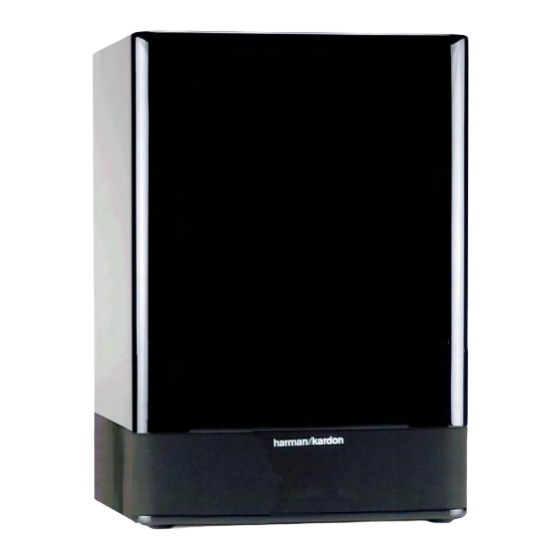
Summary of Contents for Harman Kardon SUB-TS15
- Page 1 SUB-TS15 (HKTS 15 SUBWOOFER) SERVICE MANUAL harman/kardon, Inc. 250 Crossways Park Dr. Woodbury, New York 11797 Rev0 2/2007...
-
Page 2: Table Of Contents
SUB-TS15 CONTENTS BASIC SPECIFICATIONS ... . ……………………………………..1 DETAILED SPECIFICATIONS..... . . ………………….. …2 PACKAGING. -
Page 3: Detailed Specifications
SUB-TS15 SUB-TS15 100W Powered Sub/ Plate Amp LINE VOLTAGE Yes/No Hi/Lo Line Nom. Unit Notes US 120vac/60Hz 108-132 Vrms Normal Operation Nonimal QA Test Parameter Unit Conditions Notes Specification Limits Amp Section Type (Class AB, D, other) Load Impedance (speaker) - Page 4 SUB-TS15 Nonimal QA Test Parameter Unit Conditions Notes Specification Limits Turn-off Transient mV-peak @ Speaker Outputs AC Line cycled from ON to OFF Efficiency Maximum allowable input power under nominal input voltage and frequency, in stand-by mode (HOT Stand-by Input Power Watts @ nom.
-
Page 5: Components View
SUB-TS15 PACKAGE Item Description Part Number 2 3 4 Color Label 405-000-00333-E Warranty Card 12 13 14 15 405-000-05033-E Warranty Card 16 17 18 19 406-000-05503-E Owner's Manual 20 21 22 23 24 Packaging Packaging Non-woven Bag PE Bag... -
Page 6: Controls & Connections
SUB-TS15 SUB-TS15 SUBWOOFER AMPLIFIER PANEL CONTROLS AND CONNECTIONS ¡ Subwoofer-Level Control ∞ Phase Switch ª Speaker-Level Inputs ™ High-Cut (Low-Pass) Filter Switch § Line-Level Subwoofer (SUB) Input ‚ Master Power Switch £ External Trigger Input ¶ Line-Level Full-Range Inputs ⁄... -
Page 7: Speaker Connections
ON position, the with digital surround sound decoding, such woofer output, connect these binding-post SUB-TS15 will remain on, whether or not it is as Dolby ® Digital or DTS, ®... -
Page 8: Speaker Connections
USE THIS INSTALLATION METHOD FOR – – DOLBY DIGITAL, DTS OR OTHER DIGITAL SURROUND PROCESSORS: SUB-TS15 Subwoofer Use the line-level input jack marked SUB LINE LEVEL IN § for the Low-Frequency Effects channel. Connect this jack to the subwoofer output or LFE output on your receiver or amplifier. -
Page 9: Dolby Pro Logic Non-Digital Line Level
Front Front Left Right the left or right Line-Level Full-Range Input ¶ on the SUB-TS15 subwoofer. SUB/LFE Use both the left and right inputs on the subwoofer if your receiver or processor has Surround Surround both left and right line-level outputs. - Page 10 Connect your receiver or amplifier’s front left and right speaker terminals to the left and right Speaker-Level Input ª termi- nals on the SUB-TS15 subwoofer that are marked “High Level In. ” Connect the left and right Speaker-Level Output • terminals on the SUB-TS15 subwoofer that are marked “High Level Out”...
-
Page 11: Operation
SUB-TS15’s External Trigger Input £. When you turn duce higher frequencies. This switch should be left in the ON position, except:... -
Page 12: Test Procedure
SUB-TS15 Test Set Up and Procedure Equipment needed: Function/signal generator/sweep generator • • Integrated Amplifier • Multimeter • Speaker cables Initial Control Settings: • Power Switch OFF; Filter OFF • Level MIN (Full CCW) • Phase, Auto/On switches do not matter... -
Page 13: Unit Exploded View
SUB-TS15... -
Page 14: Amplifier Exploded View
SUB-TS15... -
Page 15: Block Diagram
SUB-TS15... - Page 16 SUB-TS15...
-
Page 17: Detailed Troubleshooting
SUB-TS15 SUB-TS15 (UL) AMP Troubleshooting Flow Chart AMP no signal out Check Fuse,Transformer, D110, etc DC voltage check ±Vcc Check Q117,118,119,D109 etc Check+/-15VDC LED red LED light green or red Check,Q206,Q207,U203 etc LED light green CheckU201,U202,VR201 Check U201 VR202. etc... -
Page 18: Pcb Drawings
SUB-TS15... - Page 19 SUB-TS15...
- Page 20 SUB-TS15...
- Page 21 SUB-TS15...
- Page 22 SUB-TS15...
- Page 23 SUB-TS15...
-
Page 24: Electrical Parts List
SUB-TS15 SUB-TS15 120V Electrical parts list Part number Description Qty Reference Designator MAIN/POWER PCB Resistors 110-10821jk2-e Resistor 820Ω 1W ±5% jam crus and shaping 10mm (RoHS) R132 110-122r2j15-e Resistor 2.2Ω 1/2W ±5% prone short crus 15mm (RoHS) R127 110-20331jk2-e Resistor 330Ω... - Page 25 SUB-TS15 Part number Description Qty Reference Designator MAIN/POWER PCB 199-65001603g-e ZENER DIODE GDZJ16C 500mW 16V 26mm 2% (RoHS) D109 190-06m4558d-e I.C. OPA 4558D Dual Op-Amp U101 Transistor TIP35C NPN 192-021tip35c-e Q107 Transistor TIP36C PNP 192-022tip36c-e Q108 192-027c1815gr-e Transistor 2SC1815GR NPN...
- Page 26 SUB-TS15 Part number Description Qty Reference Designator PREAMP PCB 129-a224j633-e METALIZE CAP. 0.22uF 63V ±5% MSC (RoHS) C218 130-2b103k503-e DISC Capacitor 0.01u 50V ±10% (RoHS) C238 C200,C204,C205,C207,C208,C210,C211, 130-2b221k503-e DISC Capacitor 220P 50V ±10% (RoHS) C212,C214,C220,C230,C237 C232,C242,C244,C245,C246,C252,C254, 130-3f104z503-e DISC Capacitor 0.1U 50V +80/-20% (RoHS)
- Page 27 SUB-TS15 Part number Description Qty Reference Designator LIMITER PCB 132-103j503-e MYLAR Capacitor 0.01uF 50V ±5% (RoHS) C302,C303 Semiconductors 190-16tl074cn-e *I.C TL074CN ST QUAD OP-AMP U301 *Transistor 2SC1815GR NPN 192-027c1815gr-e Q301,Q302 197-631n4148-e Diode1N4148 26mm D301,D302 Miscellaneous 175-9f40hr2-e WIRE CONNECTOR & BASE 40PIN PITCH=2.54mm HR2*40 (RoHS)
-
Page 28: Semiconductor Pinouts
SUB-TS15... -
Page 29: Schematic Diagrams
SUB-TS15... - Page 30 SUB-TS15...
-
Page 31: Power-Amp Wiring Diagram
SUB-TS15...


Need help?
Do you have a question about the SUB-TS15 and is the answer not in the manual?
Questions and answers