
Related Manuals for Harman Kardon SUB-TS14


Summary of Contents for Harman Kardon SUB-TS14
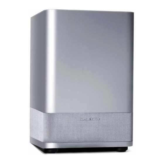
- Page 1 SUB-TS14 (HKTS 14 SUBWOOFER) SERVICE MANUAL harman/kardon, Inc. 250 Crossways Park Dr. Woodbury, New York 11797 Rev1 10/2005...
-
Page 2: Table Of Contents
SUB-TS14 CONTENTS BASIC SPECIFICATIONS ... . ……………………………………..1 DETAILED SPECIFICATIONS..... . . ………………….. …2 CONTROLS &... -
Page 3: Detailed Specifications
SUB-TS14 HKTS 14 Sub 200W Powered Sub/ Plate Amp Notes LINE VOLTAGE Yes/No Hi/Lo Line Nom. Unit US 120vac/60Hz 108-132 Vrms Normal Operation Nonimal QA Test Parameter Specification Unit Limits Conditions Notes Amp Section Bridge type amplifier, None of the... - Page 4 SUB-TS14 functional AC Power Applied sec. Power on Delay time Transients/Pops ATO Transient mV-peak @ Speaker Outputs Turn-on Transient mV-peak @ Speaker Outputs AC Line cycled from OFF to ON AC Line cycled from ON to OFF Turn-off Transient...
-
Page 5: Controls & Connections
ON position, the Level Control. Turn the control clockwise Inputs §, unless your receiver or processor SUB-TS14 will remain on, whether or not it is to increase the SUB-TS14’s volume, or processes its line-level output using a low- receiving an audio signal. - Page 6 “•” position to power-on the Switch £ is in. SUB-TS14. If your receiver has only a single SUB-TS14 subwoofer. The SUB-TS14 will ¢ Phase Switch: This switch determines subwoofer output, you may connect it to then be either in the Standby mode or com- whether the SUB-TS14 subwoofer’s piston-...
-
Page 7: Speaker Connections
USE THIS INSTALLATION METHOD FOR – – DOLBY DIGITAL, DTS OR OTHER DIGITAL SURROUND PROCESSORS: SUB-TS14 Subwoofer Use the line-level input jack marked SUB LINE LEVEL IN ∞ for the Low-Frequency Effects channel. Connect this jack to the subwoofer output or LFE output on your receiver or amplifier. - Page 8 Left Right the left or right Line-Level Full-Range SUB/LFE Input § on the SUB-TS14 subwoofer. Use both the left and right inputs on the Surround Surround subwoofer if your receiver or processor has...
- Page 9 Connect your receiver or amplifier’s front left and right speaker terminals to the left and right Speaker-Level Input • termi- nals on the SUB-TS14 subwoofer that are marked “High Level In. ” Connect the left and right Speaker-Level Output ¶ terminals on the SUB-TS14 subwoofer that are marked “High Level Out”...
-
Page 10: Operation
(marked Power) to the “ • ” (On) position. Volume can be adjusted using the Sub- In addition to the volume adjustments The SUB-TS14 subwoofer will automatically woofer-Level Control ¡, as shown. described above, the SUB-TS14 subwoofer turn itself on or go into Standby mode, includes a Phase Switch ¢... -
Page 11: Basic Troubleshooting Guide
• If more than one pair of main speakers is being used, check the minimum impedance requirements of your receiver/amplifier. If there is low (or no) bass • Make sure the SUB ∞ or Line-Level Inputs § of the SUB-TS14 subwoofer and SUB or LFE output of your receiver output: or amplifier are properly connected by the RCA-type interconnect cable. -
Page 12: Test Procedure
SUB-TS14 Test Set Up and Procedure Equipment needed: Function/signal generator/sweep generator • • Integrated Amplifier Multimeter • • Speaker cables Initial Control Settings: Power Switch OFF; Filter OFF • • Level MIN (Full CCW) Phase, Auto/On switches do not matter •... -
Page 13: Unit Exploded View
SUB-TS14 Ref# Description Part Number Amplifier screw 352-AM04020D210 SUB-TS14 Amplifier Not for Sale Port Tube Not for Sale SUB-TS14 Cabinet Not for Sale Logo 316-AG-00557 Not for Sale Grille Not for Sale Logo 316-AL-00553 12" woofer 30PF14FM-DW05 Woofer screw... -
Page 14: Amplifier Exploded View
SUB-TS14 (See Mechanical Parts List on Pages 22-23) -
Page 15: Block Diagram
SUB-TS14... -
Page 16: Pcb Drawings
SUB-TS14... - Page 17 SUB-TS14...
- Page 18 SUB-TS14...
- Page 19 SUB-TS14...
-
Page 20: Electrical Parts List
SUB-TS14 SUB-TS14 120V Electrical parts list Part number Description Qty Reference Designator PREAMP PCB Resistors 110-12472j52 Resistor 4.7K 1/2W ±5% CF 52mm R201,202 110-16102j26 Resistor 1K 1/6W ±5% CF 26mm R213,214,215,254 R209,212,216,217,218,220,221,222,225,228,229,230, 110-16103j26 Resistor 10K 1/6W ±5% CF 26mm 232,235,240,248,260,270 Resistor 100K 1/6W ±5% CF 26mm... - Page 21 SUB-TS14 Part number Description Qty Reference Designator PREAMP PCB Miscellaneous 162-50332003 2 PIN 330mm RED D209 174-0rca313v RCA JACK RCA-313G V/R/W JK201 174-20810360g JACK SPK JK BP 8PIN JK202 175-1b08v01 wire connector 8 PIN PITCH=2.0mm W202 175-1c07v01 wire connector 7 PIN PITCH=2.5mm...
- Page 22 SUB-TS14 Part number Description Qty Reference Designator MAIN PCB 135-3106m50 electrolytic 10uF 50V ±20% C319,321 135-3107m10 electrolytic 100U 10V ±20% C114,115 135-3107m35 electrolytic 100U 35V ±20% C507,508 135-3225m50 electrolytic 2.2U 50V ±20% C509 135-3226m16 electrolytic 22U 16V ±20% C304 135-3226m50 electrolytic 22U 50V ±20%...
- Page 23 SUB-TS14 Part number Description Qty Reference Designator Power Amp Class D Module part# 012-7500-00022 RECOMMENDED: REPLACE ENTIRE MODULE 118-12064701j SMD Resistor 4.70K 1206 5% R1,5,12 118-12064702j SMD Resistor 47.0K 1206 5% 118-12064704j SMD Resistor 4.70M 1206 5% 118-120647r0j SMD Resistor 47.0Ω 1206 5%...
- Page 24 SUB-TS14 Part number Description Qty Reference Designator MISCELLANEOUS/MECHANICAL 317-000-00037 Ground terminal M3 t=0.3 333-EVA-00096 EVA (gasket) 213*15*2.0mm 333-EVA-00097 EVA (gasket)213*15*1.0t 333-EVA-00121 8PIN BB EVA (gasket) 333-EVA-00132 EVA (gasket) 238*15*2.0mm 333-EVA-00133 EVA (gasket)238*15*1.0t 333-EVA-00188 EVA (gasket) 170x5x1t 333-EVA-00219 EVA (gasket)150*15*1t UL...
-
Page 25: Semiconductor Pinouts
SUB-TS14... -
Page 26: Schematic Diagrams
SUB-TS14... - Page 27 SUB-TS14...
- Page 28 SUB-TS14...
Need help?
Do you have a question about the SUB-TS14 and is the answer not in the manual?
Questions and answers