Table of Contents
Advertisement
Quick Links
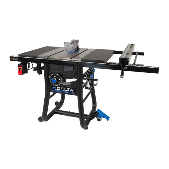
36-725 T2 Quick Assembly Guide
PACKAGE CONTENTS
PC1
PC2
PC4
36-725 T2 Saw Body
PC1
Left Leg (B)
PC2
Right Leg (A)
PC3
Rip Fence
PC4
Blade Guard
PC5
Miter Gauge
PC6
Push Stick
PC7
Throat Plate
PC8
PC3
Blade Wrench
PC9
Extension Wings (2)
PC10
Anti-Kickback Pawls
PC11
Adjustable Feet (2)
PC12
Fixed Wheels (2)
PC13
Hand Wheel Handle (2)
PC14
Rip Fence Handle
PC15
10 inch Blade (Pre-Installed)
PC16
PC11
PC5
PC12
PC6
PC13
PC7
PC14
PC15
PC8
PC9
PC16
PC10
Rail Spreader Bar
PC17
Rear Fence Rails (2)
PC18
Front Fence Rails (2)
PC19
Fence Guides (2)
PC20
PC17
PC18
PC19
PC20
Advertisement
Table of Contents

Related Manuals for Delta 36-725 T2


Summary of Contents for Delta 36-725 T2
- Page 1 36-725 T2 Quick Assembly Guide PACKAGE CONTENTS PC17 PC11 PC12 PC13 PC14 PC15 PC18 PC19 PC20 PC16 PC10 Rail Spreader Bar 36-725 T2 Saw Body Blade Wrench PC17 Rear Fence Rails (2) Left Leg (B) Extension Wings (2) PC18 PC10...
-
Page 2: Hardware Package
HARDWARE PACKAGE Hardware Bag “D” Hardware Bag “B” Hardware Bag “A” 006291 005733 006109 006134 003578 005733 005733 003059 003331 HP10 006292 006293 HP11 HP12 006122 Hardware Bag “C” 006108 005679 006111 006109 HP13 HP15 Hardware Bag “F” Hardware Bag “E ” 004623 006113 HP16... -
Page 3: Fixed Wheels And Stationary Feet
TOOLS REQUIRED FOR ASSEMBLY (NOT INCLUDED): • 9/16 inch Wrench • Flat Head Screwdriver • 5/32 inch Allen Wrench • Phillips Head Screwdriver • Framing (Carpenter's) Square • 8mm Wrench • Combination Square • 10mm Wrench • Straight Edge • 12mm Open-Ended Wrench •... -
Page 4: Step 3: Front And Rear Rails
Step 3: FRONT AND REAR RAILS Hardware Bag “D” Attach the Front Fence Rails (1&2) to the Table Front PC19 using (4) 5/16-18 x 1-1/8 inch Flat Countersunk Hex Screw HP13 , and (4) 5/16-18 Hex Flange Nuts , see Figure 5 PC19 HP15 HP13... -
Page 5: Step 4: Extension Wings
Step 4: EXTENSION WINGS Hardware Bag “C,D” Attach the Extension Wings to the Table using (6) 5/16-18 PC10 x 7/8 Hex Screw with Split Lock Washers , (3) for each Wing. The Wings attach from underneath as shown in Figure 10. -
Page 6: Step 5: Fence Guide And Power Control Box
Step 5: FENCE GUIDE AND POWER CONTROL BOX RIGHT FENCE Hardware Bag “E” GUIDE (LONG) PC20 Attach the Right Fence Guide using (3) 1/4-20 x 1/2 PC20 inch Button Head Hex Screw with Split Lock Washers HP18 through the holes on the bottom side of the Front Rail. See Figure 13. -
Page 7: Installing The Handles
Step 6: INSTALLING THE HANDLES Elevation and Bevel Hand Wheels The elevation and Bevel Handles are packaged together in the box, please install as follows: Insert one Handle to the Elevation Hand Wheel located PC14 in the front of the Saw, as seen in Figure 17. Insert one Handle to the Bevel Hand Wheel located on PC14... -
Page 8: Step 10: Anti-Kickback Pawls
Step 10: ANTI-KICKBACK PAWLS To reduce the risk of serious personal injury, Anti-Kickback Pawls MUST be in place when making a through cut See Figure 22 and locate the Anti-Kickback Pawls Mounting Slot in the middle of the top edge of the Riving Knife. Slide Slot in the middle of the Anti-Kickback Pawls Assembly along the top of the Riving Knife until the stem locates the center slot...