Unitech MR650 Product Reference Manual
Hide thumbs
Also See for MR650:
- Specifications (2 pages) ,
- Programming manual (66 pages) ,
- User manual (39 pages)
Table of Contents
Advertisement
Quick Links
Advertisement
Table of Contents

Related Manuals for Unitech MR650


Summary of Contents for Unitech MR650
- Page 1 Unitech MR650 Product Reference Guide...
-
Page 2: About This Manual
Preface About This Manual This manual explains how to install, operate and maintain the MR650 TAS Terminal. No part of this publication may be reproduced or used in any form, or by any electrical or mechanical means, without permission in writing from the manufacturer. This includes electronic or mechanical means, such as photocopying, recording, or information storage and retrieval systems. -
Page 3: Notices
Notices The Unitech MR650 is equipped with a Lithium-Ion battery pack, however as a result of storage it’s possible that the unit will not power-on due to battery discharge. If this occurs, connect the MR650 to the power adapter and plug into a standard electrical outlet. -
Page 4: Table Of Contents
Supply Power to MR650 ........ - Page 5 Chapter 2 Using the Hardware Using the Keypad & Reader ..........18 Rubber Keypad .
- Page 6 Chapter 5 Useful Utilities Scanner Setting ............33 Scan2Key .
-
Page 7: Getting Started
The unit can communicate with central host security and T&A systems via standard Ethernet or WLAN networks. The MR650 also provides the ability to seize complete control over area security with a built-in CMOS digital camera, microphone, and audio speaker. -
Page 8: Support
Chapter 1 Getting Started Support Unitech’s professional support team is available to quickly answer your questions or technical-related issues. Should an equipment problem occur, please contact the Unitech regional service representatives nearest you. Please go to their websites, listed below, for complete contact information: UTC (China) http://www.ute.com.cn... -
Page 9: Features
Features System Barcode Reader • Microsoft Windows CE 5.0 • Unitech decoder chip Professional Operating System • Supports: China Postal Code, • Intel PXA270 520MHz Processor Codabar, Code 11, Code 32, Code 39, Code 93, Code 128, System Memory Delta Code Interleaved 2 of 5, •... -
Page 10: Package Contents
Chapter 1 Getting Started Package Contents After opening the box, ensure the following items for the MR650 are present: Unitech MR650 Quick Start Guide MR650 Main Body Manual CD Stylus RS232 Cable AC Power Adapter... -
Page 11: A Tour Of The Mr650
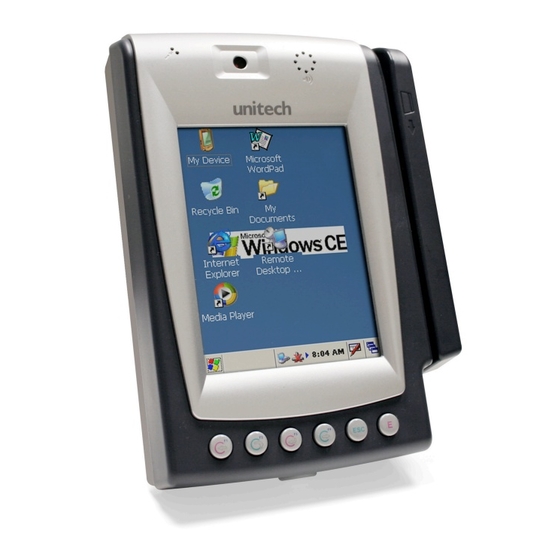
Chapter 1 Getting Started A Tour of the MR650 The following sections describe the main components and features of the MR650. Front View: Proximity/Biometric Reader (left), Slot Reader (right) Component Description Speaker Enables you to hear recorded audio. CMOS Camera Allows photo to be captured when a card is read. -
Page 12: Back View
Chapter 1 Getting Started Back View Component Description Front Case Hook Connects the unit and the back panel. Terminal Block Supplies DC power to main board. Mounting Hole Allows for wall mounting. Key Lock Gives access to internal circuit board. -
Page 13: First Steps With Mr650
To power on the MR650, plug the 12V DC power adaptor into the DC Connector’s Terminal Block, which is located on the inner side of the back panel. The MR650 can operate while the backup battery is being charged. A full charge of the battery typically takes 22 hours. -
Page 14: Supply Power To Mr650
Chapter 1 Getting Started Supply Power to the MR650 Insert key into lock and turn Lift back plate up 45˚ degrees counter-clockwise to unlock Plug 12V DC to terminal block and turn Push switch down to “on” position battery switch on to charge battery... -
Page 15: Protective Screen Film
A screen will automatically appear when the unit is powered-on for the first time or after the system is reset. The MR650 will prompt you to calibrate the unit by tapping a sequence of screen locations. Tap gently but firmly. When you have completed the series of taps, press the [ENT] key to confirm, or press the [ESC] key to cancel the operation. -
Page 16: Setting The Time Zone/Date
Chapter 1 Getting Started Setting the Time Zone/Date After calibrating the MR650, the “Date/ Time Properties” dialog box will appear. Setting the Time Zone Follow the steps below to set up your time zone. 1. Tap the location arrow to see a list of cities. -
Page 17: Setting The Date/Time
Chapter 1 Getting Started After calibrating the MR650, the “Date/ Time Properties” dialog box will appear. Setting the Date/Time Tap the left or right arrows to scroll the year and month you desire, or directly tap the location of year or month to change the setting. -
Page 18: Using The Hardware
Using the Hardware Using the Keypad and Readers Rubber Keypad The MR650 keypad contains 6 rubber keys, including F1~F4, ESC and ENTER key. Please refer to below picture. [F1]~[F4] Standard Windows CE function key [ESC] This key will perform the same function as tapping the CANCEL button or X button on the touch screen. -
Page 19: Software Keyboard
Using the Hardware Software Keyboard Since the MR650’s rubber keypad allows input of numeric characters only, the Windows CE software provides a touch screen keyboard for input of other characters. The windows based keyboard replicates the layout of a standard PC keyboard. -
Page 20: Using The Readers
Testing Reader’s Data The MR650 has a built-in Scanner Settings.EXE program that allows the user to test the reader’s data. To access the program go to the Start menu, locate the Control Panel, double click the “Scanner Settings” icon, click on “Test”. The reading data will... -
Page 21: Using Finger Print Reader
Chapter 2 Using the Hardware Using the Fingerprint Reader The MR650 with the Fingerprint Reader can hold up to 4000 templates. The verifying time with the maximum amount of templates will be less then 2 seconds. Place finger here... -
Page 22: Testing Fingerprint Verification
Using the Hardware Testing Fingerprint Verification The MR650 has a built-in BIOIDMgr.EXE program that allows the user to test the finger print verification. The program is accessible via the “My Device” icon on the Windows CE desktop. Locate the Windows folder, double click on the “BIOIDMgr” icon, the finger print verification will appear on the screen. -
Page 23: Enroll Fingerprint Stamp
Chapter 2 Using the Hardware Enroll Fingerprint Stamp Click on “Enroll”, enter an ID number for the fingerprint, click on “OK”, the message “Place finger on sensor” will appear. Place the finger on the sensor and the fingerprint will be tagged with a quality percentage and an ID number and will be saved in the system. -
Page 24: Verify Fingerprint Stamp
Chapter 2 Using the Hardware Verify Fingerprint Stamp To verify a Fingerprint Stamp click on “Verify”, enter a fingerprint ID number, click on “OK”, and the message, “Place finger on sensor” will appear. Place a finger on the sensor to verify the fingerprint. The fingerprint’s quality percentage number will appear on the screen with a “Pass”... -
Page 25: Using The Camera
Using the Hardware Using the Camera The MR650 has a built-in 1.3 mega pixel camera, allowing a photo to be captured when a card is read, documenting attendant time with a photo image. Continuous audio/video recording is capable with the onboard camera and microphone. -
Page 26: Testing The Camera
Using the Hardware Testing the Camera The MR650 has a built-in Camera Demo.EXE program that allows the user to see the imager. The Camera Demo program is accessible via the “My Device” icon on the Windows CE desktop. Locate the Windows folder, double click on the “Camera Demo”... -
Page 27: Power System
More power is consumed when the backlight is used at 100% brightness and the fingerprint function is in use. When the MR650 is out of external power the terminal will go into sleeping mode and the backlight will turn off. Once the panel is touched the backlight will be on minimum brightness to conserve power. -
Page 28: Backlight Setting
Power System Backlight Setting Screen Contrast The MR650’s screen contrast has been set by the factory manufacturer and cannot be adjusted by the end user. Screen Backlight The backlight for the color display is adjustable. To adjust the Backlight settings go to “My Device”... -
Page 29: Warm Start/ Cold Start
Chapter 3 Power System Warm Start / Cold Start Warm Start Warm Start re-boots the device without losing SD RAM data. You would perform a warm start when the following happens: • The terminal fails to respond • After installing some software applications •... -
Page 30: Data Communication
Chapter 4 Data Communication The MR650 allows users to link to a host computer via RS232, Ethernet, or RF connection for data communication. Connecting Serial Cable Plug the RS232 communication cable into the PC’s 9 pin Com Port and the other end into the MR650’s RS232 interface port. -
Page 31: Rf Communication
Chapter 4 Data Communication RF Communication Insert CF card for 802.11b/g wireless communication. Windows CE can support TCP/IP protocol. The user can link to the Internet via the start menu, under “Settings” then “Network and Dial-up Connections”. Under “Network and Dial-up Connections”, go to DM9ISA1 to set up the IP to connect to internet. -
Page 32: Use Activesync
Requirements To synchronize, ActiveSync version 4.1 or higher must be installed on both your desktop computer and the MR650 terminal. The MR650 terminal ships with ActiveSync already installed. Therefore, you must install ActiveSync 4.1 on your desktop computer. -
Page 33: Useful Utilities
Chapter 5 Useful Utilities Scanner Settings When the user needs to change the default barcode symbologies for a different application the Scanner Control Panel provides the setting function to change default symbologies, place delimiter characters behind scanned data, and save the settings. To run the Scanner Control Panel go to Start\Setting\Control Panel\Scanner Setting.exe. -
Page 34: Registry Backup/Restore
Chapter 5 Useful Utilities Registry Backup/Restore The Registry Backup/Restore program gives the user the ability to save and recall the initial changes made to Settings. For example, if a cold boot was performed the user can go to the Registry Backup to retrieve the original settings. -
Page 35: Audio Demo Program
Chapter 5 Useful Utilities Audio Demo Program The Audio Demo program allows you test audio input and output which can record and playback voice recordings. The Audio Demo program is accessible via the “My Device” icon on the Windows CE desktop. Locate the Windows folder, double click on the “wavtest”... -
Page 36: Softkeys
Chapter 5 Useful Utilities Softkeys Softkeys is the numeric on-screen keypad utility to input numeric keys. To run Softkeys go to \Start\Program\Utilities\Softkeys. -
Page 37: Terminal Block
Chapter 6 Terminal Block Overview of Terminal Block 4 digital 12V DV 3 relays Flex cable to inputs power in main board... -
Page 38: Terminal Block Pin Assignment
Chapter 6 Terminal Block Terminal Block Pin Assignment 1-------------------10 Name Description DC Out Support +12V, 0.5A DI1-L Photo-In Anode(-) D11-H Photo in Cathode(+) DI2-L Photo-In Anode(-) DI2-H Photo in Cathode(+) DI3-L Photo-In Anode(-) DI3-H Photo in Cathode(+) DI4-L Photo-In Anode(-) DI4-H Photo in Cathode(+) Name...
Need help?
Do you have a question about the MR650 and is the answer not in the manual?
Questions and answers