Table of Contents
Advertisement
Available languages
Available languages
Model
Modèle
Modelo
INSTRUCTION MANUAL AND SAFETY INSTRUCTIONS
Improper and unsafe use of this power tool can result in death or serious bodily injury!
This manual contains important information about product safety. Please read and understand
this manual before operating the power tool. Please keep this manual available for others before
they use the power tool.
MODE D'EMPLOI ET INSTRUCTIONS DE SECURITE
Une utilisation incorrecte et dangereuse de cet outil motorisé peut entraîner la mort ou de
sérieuses blessures corporelles!
Ce mode d'emploi contient d'importantes informations à propos de la sécurité de ce produit.
Prière de lire et d'assimiler ce mode d'emploi avant d'utiliser l'outil motorisé. Garder ce mode
d'emploi à la disponibilité des autres utilisateurs avant qu'ils utilisent I'outil motorisé.
MANUAL DE INSTRUCCIONES E INSTRUCCIONES DE SEGURIDAD
¡La utilización inapropiada e insegura de esta herramienta eléctrica puede resultar en lesiones
serias o en la muerte!
Este manual contiene información importante sobre la seguridad del producto. Lea y comprenda
este manual antes de utiIizar la herramienta eléctrica. Guarde este manual para que puedan
leerlo otras personas antes de que utilicen la herramienta eléctrica.
CB 13F
WARNING
AVERTISSEMENT
ADVERTENCIA
Band Saw
Scie a bande
Sierra de cinta
Advertisement
Table of Contents

Subscribe to Our Youtube Channel
Related Manuals for Hitachi CB 13F


Summary of Contents for Hitachi CB 13F
- Page 1 Model Band Saw CB 13F Modèle Scie a bande Modelo Sierra de cinta INSTRUCTION MANUAL AND SAFETY INSTRUCTIONS WARNING Improper and unsafe use of this power tool can result in death or serious bodily injury! This manual contains important information about product safety. Please read and understand this manual before operating the power tool.
-
Page 2: Table Of Contents
Liste des pièces ..............65 Glossaire des termes ............31 CENTRES TECHNIQUES HITACHI AGREES La réparation est réalisée dans le cadre de cette garantie par Hitachi Koki U.S.A., Ltd. : AUX ETATS-UNIS AU CANADA 3950 Steve Reynolds Blvd. Norcross, GA 30093 6395 Kestrel Road Mississauga, ON L5T 1Z5 9409 Owensmouth Ave. -
Page 3: Products Specifications
English WARNING Some dust created by power sanding, sawing, grinding, drilling and other construction activities contains chemicals known to the state of California to cause cancer, birth defects or other reproductive harm. Some examples of these chemicals are: • Lead from lead-based paints •... -
Page 4: Safety
Safety is a combination of common sense, staying alert impact–resistance lenses. They ARE NOT safety and knowing how to use this Band Saw. glasses. Safety Goggles are available at HITACHI. NOTE: Glasses or goggles not in compliance with WARNING ANSI Z87.1 could cause serious injury. -
Page 5: Electrical Requirements
English 24. DO NOT OPERATE the tool if you are under the 14. CUT only one work-piece at a time. Make sure the influence of any drugs, alcohol or medication that table is clear of everything except the work-piece and could affect your ability to use the tool properly. -
Page 6: Guidelines For Extension Cords
English IN THE EVENT OF A MALFUNCTION OR BREAKDOWN, Fig. A grounding provides a path of least resistance for electric 3-Prong Plug current and reduces the risk of electric shock. This tool is equipped with an electric cord that has an equipment- grounding conductor and a grounding plug. -
Page 7: Accessories And Attachments
English ACCESSORIES AND ATTACHMENTS RECOMMENDED ACCESSORIES Use only accessories designed for this band saw to WARNING avoid injury from thrown broken parts or workpieces. Do not use any accessory unless you have completely read the instruction or operator’s manual for that To avoid injury: accessory. - Page 8 English UNPACKING YOUR BAND SAW — 8 —...
-
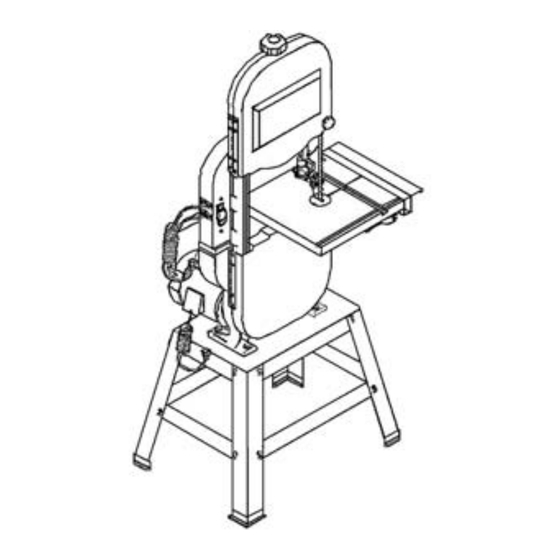
Page 9: Know Your Band Saw
English KNOW YOUR BAND SAW Blade tension knob Lower blade Upper blade wheel support bearing Blade guard Lower blade guide Upper blade support bearing Upper blade guide Upper Table insert Miter gauge cover Table aligning pin ON/OFF switch Table removed for clarity of illustration Tilt bevel scale Lower blade wheel... -
Page 10: Glossary Of Terms
English GLOSSARY OF TERMS BAND SAW TERMS KERF — The material removed by the blade in a through cut, or the slot produced by the blade in a non-through or BLADE GUIDES — Support the blade and keep it from partial cut. -
Page 11: Assembly And Adjustments
English ASSEMBLY AND ADJUSTMENT ESTIMATED ASSEMBLY TIME 35~50 MINUTES WARNING ASSEMBLY INSTRUCTIONS Although compact, this saw is heavy. To avoid back injury, get help to lift the saw. Philips screwdriver ASSEMBLE BAND SAW TO LEG STAND (Fig. B) Combination square Lift the saw body (1) and place on the leg stand (2), aligning the mounting holes (3) of the saw base with the four mounting holes of the leg stand top plate. - Page 12 English Turn the table right side up. Fig. C Remove the table insert (13) from the table. Guide the table slot (14) over the saw table and rotates 1/4 turn, so the slot is perpendicular to the blade. Placing the scale lock knob bolts (10) through the trunnion bracket holes (15) as shown, lower the table onto the trunnion bracket.
- Page 13 English INSTALLING AND REMOVING THE BLADE(Fig.G) Installing WARNING! Make sure the blade tension knob (1) turned To avoid injury from accidental starting, always turn the counterclockwise until it stops. switch OFF and remove the plus from the power source Remove old blade as explained in “Removing”. before moving, replacing, or adjusting the blade.
- Page 14 English INSTALL POWER BCORD BRACKETS (Fig. I) ADJUSTING THE 90° TABLE STOP (Fig. K) Power cord brackets (1) are provided for convenient Loosen the table lock knobs (2) and tilt the table to the cord storage. Attach the power cord brackets to the right.
- Page 15 English BLADE TENSION(FIG. L) If the blade moves toward the front of the wheel, turn the tracking knob (5) on the rear of the band saw clockwise. This tilts the top of the wheel and moves WARNING the blade toward the center. If the blade moves toward the back edge, turn the To avoid injury, turn the switch OFF and disconnect the tracking knob counterclockwise, moving the blade...
- Page 16 English UPPER BALDE GUIDES AND BLADE SUPPORT BEARING Fig. P (Fig. O, P) WARNING The blade guard has been removed for clarity of illustration. To avoid injury never operate the band saw without all guards in place and in working order. To avoid injury, turn the switch OFF and disconnect the saw from the power source before making any adjustments.
-
Page 17: Operation
English Support bearing (Fig. R) Place a straight edge in the front groove of both Loosen the bearing hex socket screw (7) with the hex pulleys, behind the blade wheel. wrench. Turn the hex socket screw (1) in the side of the motor Move the blade support bearing shaft (8) in or out pulley (2) to loosen the pulley on the shaft. - Page 18 English Release both cam locking levers. CUTTING CURVES Slide the table extension on the side your workpiece When cutting curves, carefully turn the workpiece so the will be needing support, and tighten both cam locking blade follows without twisting, If the curve is so sharp that levers.
- Page 19 English Common causes of blade breakage: CHANGING SPEED SETTING (Fig. X) Poor guide alignment and adjustment. Forcing or twisting a wide blade around a short WARNING radius. Feeding too fast. To avoid injury, turn the switch OFF and disconnect the Dull teeth or not enough set.
-
Page 20: Section Page
English MAINTENANCE GENERAL MAINTENANCE WARNING WARNING To avoid injury, the blade tension, tracking, and upper and lower guides and bearings must be properly adjusted For your own safety, turn switch OFF and remove the before operating the band saw. (See ADJUSTNEBT plug from power source receptacle before INSTRUCTIOONS section) maintaining, cleaning, adjusting, or lubricating your... -
Page 21: Troubleshooting Guide
To avoid injury from an accidental start, turn the switch OFF and remove the plug from the power source before making any adjustments. All electrical or mechanical repairs should be done only by qualified service technicians. Contact Hitachi Authorized Service Center. - Page 22 English MOTOR PROBLEM PROBABLE REMEDY Noisy operation. 1. Incorrect belt tension. 1. Adjust tension. See ASSEMBLY AND ADJUSTMENTS section INSTALL THE BELT. 2. Readjust and tighten motor pulley set screw. 2. Loose motor pulley. 3. Readjust and tighten pulley cover 3.
-
Page 23: Spécifications Produit
Français AVERTISSEMENT La poussière engendrée par le sablage, le sciage, le broyage et le forage électriques et autres activités de construction contient des agents chimiques qui, selon l’Etat de Californie, sont susceptibles de provoquer le cancer, des malformations de naissance ou autres troubles de la reproduction. Parmi les exemples des agents chimiques: •... -
Page 24: Sécurité
Ce NE SONT PAS des verres de sécurité. Vous pouvez vous procurer des MAINTENEZ LES DISPOSITIFS DE PROTECTION EN lunettes de sécurité auprès d’HITACHI. PLACE et en état de marche. NOTE: Les lunettes ou les verres non conformes à... - Page 25 Français 20. NE JAMAIS LAISSER L’OUTIL EN MARCHE SANS UTILISEZ DES POINTS DE SUPPORT SUPPLEMENTAIRES SURVEILLANCE. METTEZ-LE EN POSITION “ARRET”. pour empêcher les pièces de glisser de la table. Ne Ne lâchez pas l’outil avant son arrêt complet. demandez jamais à une autre personne de maintenir la pièce à...
- Page 26 Français UN RACCORDEMENT INCORRECT du conducteur de mise AVERTISSEMENT à la masse de l’outil électrique peut se traduire par un choc électrique. Le conducteur dont l’isolant est vert (avec Pour votre sécurité, lisez tout le manuel d’instruction ou sans filets jaunes), est le conducteur de mise à la avant de faire fonctionner la scie à...
- Page 27 Français Fig. A Prise à 3 bornes Borne de mise à la masse Prise à 3 bornes correctement mise à la masse Fig. B Cosse de mise à la masse S'assurer que ceci est bien relié à une masse connue Prise à...
-
Page 28: Accessoires
Français ACCESSOIRES Utilisez uniquement les accessoires conçus pour cette ACCESSOIRES RECOMMANDES scie à bande pour éviter tout risque de blessure provenant de la rupture des pièces ou des pièces AVERTISSEMENT usinées. N’utilisez aucun accessoire sans avoir lu les instructions ou le manuel de l’opérateur de ces Pour éviter toute blessure: accessoires. - Page 29 Français DEBALLAGE DE LA SCIE A BANDE — 29 —...
-
Page 30: Connaître Votre Scie A Bande
Français CONNAITRE VOTRE SCIE A BANDE Bouton de tension de la lame Roue supérieure Palier-support de la lame inférieur de la lame Protège-lame Guide-lame inférieur Palier-support supérieur de la lame Guide-lame supérieur Insert de table Couvercle Guide pour coupe d’onglet supérieur Broche d’alignement de la table Interrupteur... -
Page 31: Glossaire Des Termes
Français GLOSSAIRE DES TERMES TALON — Mauvais alignement de la lame. TERMES RELATIFS A LA SCIE A BANDE VOIE — Matériau ôté par la lame dans une coupe GUIDES LAMES — Soutiennent la lame et l’empêchent de complète, ou fente produite par la lame dans une coupe se tordre pendant l’utilisation. -
Page 32: Montage Et Réglage
Français MONTAGE ET REGLAGE TEMPS D’ASSEMBLAGE ESTIME A 35~50 MINUTES AVERTISSEMENT INSTRUCTIONS DE MONTAGE Même si elle est compacte, la scie est lourde. Pour éviter de vous faire mal au dos, demandez de l’aide pour soulever la scie. Tournevis Philips Equerre combinée MONTAGE DE LA SCIE A BANDE AU PIED (Fig. - Page 33 Français Retournez la table à l’endroit. Fig. C Ôtez l’insert de table (13) de la table. Guidez la fente de la table (14) sur la table et tournez d’1/4 de tour, de manière à ce que la fente soit perpendiculaire à la lame. En plaçant les boulons du bouton de verrouillage (10) à...
- Page 34 Français INSTALLATION ET DEMONTAGE DE LA LAME (Fig. G) AVERTISSEMENT ATTENTION ! Pour éviter tout risque de blessure provenant d’un démarrage accidentel, mettez toujours l’interrupteur sur la Avant l’opération, vérifiez toujours que la lame se trouve position ARRET et débranchez la prise d’alimentation au centre de la fente de l’insert de table.
- Page 35 Français INSTALLATION DES PATTES DU CORDON REGLAGE DU BOULON D’ARRET DE LA TABLE A 90° D’ALIMENTATION (Fig. I) (Fig.K) Des pattes pour cordon d’alimentation (1) sont Desserrez les boutons de verrouillage de la table (2) et fournies pour un rangement pratique du cordon. Fixez inclinez la table vers la droite.
- Page 36 Français TENSION DE LA LAME (Fig. L) Faites lentement tourner à la main la roue (4) vers l’avant et vérifiez la position de la lame sur la roue. La lame en mouvement doit rester centrée sur la roue. AVERTISSEMENT Si la lame se déplace vers l’avant de la roue, tournez le bouton du sillage (5) à...
- Page 37 Français GUIDES DE LA LAME ET PALIER-SUPPORT SUPERIEURS Fig. P DE LA LAME (Fig. O, P) AVERTISSEMENT La protection de lame n’est pas figurée à des fins de clarté d’illustration. Pour éviter toute blessure, n’utilisez jamais la scie à bande sans que toutes les protections soient en place et en état de marche.
-
Page 38: Utilisation
Français Palier-support (Fig. R) Placez une règle droite dans la gorge avant des deux Desserrez la vis à tête hex du palier (7) à l’aide d’une poulies, derrière la roue de la lame. clé. Tournez la vis à tête hex (1) dans le côté de la poulie Faites jouer l’arbre du palier-support de la lame (8) du moteur (2) pour desserrer la poulie sur l’arbre. - Page 39 Français B. Pour le sciage en long d’une pièce à usiner de 7-1/2”~ COUPE DE COURBES 12”, vous devez installer la garde de rallonge en Pour la coupe de courbes, tournez soigneusement la pièce position OUT-RIP. à usiner de manière à ce que la lame suive sans se tordre. Déverrouillez les deux leviers de verrouillage à...
- Page 40 Français Ne vous servez pas de cette scie à bande pour couper des MODIFICATION DU REGLAGE DE LA VITESSE (Fig. X) métaux ferreux. AVERTISSEMENT Principales raisons de cassure de la lame: Mauvais alignement et réglage des guides. Forçage ou torsion d’une lame épaisse autour d’un Pour éviter tout risque de blessure, mettez l’interrupteur petit rayon.
-
Page 41: Entretien
Français ATTENTION: Pour la coupe de métaux non ferreux, les Nettoyez toute trace de sciure à l’intérieur de la copeaux de métal peuvent réagir avec la sciure et générer scie. un incendie. Pour éviter cela : Nettoyez tous les copeaux de métal à l’intérieur de Déconnectez un éventuel tuyau d’évacuation de la la scie avant de scier à... -
Page 42: Guide De Résolution Des Pannes
Pour éviter tout accident du à un démarrage accidentel, mettez l’interrupteur sur ARRET et débranchez toujours la prise de la prise secteur avant de procéder à des réglages. Toutes les réparations électriques ou mécaniques doivent être réalisées uniquement par des techniciens qualifiés. Contactez le centre d’entretien autorisé Hitachi. GENERALITES PROBLEME... - Page 43 Français MOTEUR PROBLEME CAUSE PROBABLE SOLUTION Fonctionnement bruyant. 1. Tension de la courroie incorrecte. 1. Réglez la tension. Veuillez vous référer à la section INSTALLATION DE LA COURROIE dans MONTAGE ET REGLAGES. 2. Réglez à nouveau et serrez la vis de pression de la 2.
-
Page 44: Español
Español ADVERTENCIA Según ha sabido el estado de California, en ocasiones, el polvo que se crea al pulir, serrar, moler, perforar o llevar a cabo otras actividades de construcción con herramientas eléctricas contiene sustancias químicas que pueden causar cáncer, defectos de nacimiento u otros daños relacionados con la reproducción. Algunos ejemplos de estas sustancias químicas son: •... -
Page 45: Seguridad
ANSI. Las gafas normales tan sólo son resistentes no enchufe la sierra de cinta hasta que no haya leído y a los impactos. NO son gafas de seguridad. HITACHI entendido las siguientes normas de seguridad: dispone de gafas protectoras de seguridad. - Page 46 Español 22. MANTENGA LAS HERRAMIENTAS EN PERFECTAS pequeñas con cuidado para evitar pellizcar la hoja. CONDICIONES. Mantenga las herramientas afiladas y Evite posiciones incómodas de las manos para evitar limpias para que rindan al máximo y ofrezcan la el contacto accidental con la hoja. mayor seguridad.
- Page 47 Español Utilice un circuito eléctrico independiente para sus REQUISITOS ELÉCTRICOS herramientas. Este circuito no deberá ser inferior a un FUENTE DE ALIMENTACIÓN Y ESPECIFICACIONES DEL cable de calibre 12 y debe estar protegido mediante un MOTOR fusible de retardo de 15 amperios. Antes de conectar el motor a la toma de corriente, asegúrese de que el ADVERTENCIA interruptor está...
-
Page 48: Accesorios
Español Asegúrese de que el cable prolongador está ADVERTENCIA correctamente conectado y en buen estado. Si el cable prolongador resulta dañado, cámbielo inmediatamente o encargue su reparación a una persona cualificada antes Esta sierra de cinta está prevista únicamente para su uso de utilizarlo. - Page 49 Español ELEMENTO DESCRIPCIÓN CANTIDAD ELEMENTO DESCRIPCIÓN CANTIDAD Ganchos del cable de alimentación PEDESTAL: Almohadillas para los pies Tablero del pedestal Perno hexagonal Travesaños inferiores cortos Perno hexagonal Travesaños inferiores largos Botones Patas Llave hexagonal Bolsa: Tornillos Pernos de cabeza redonda Perno hexagonal largo Tuercas hexagonales Tuercas hexagonales...
-
Page 50: Conozca Su Sierra De Cinta
Español CONOZCA SU SIERRA DE CINTA Pomo de tensión de la hoja Cojinete de apoyo Rueda de la de la hoja inferior hoja superior Protector de la hoja Guía de la hoja inferior Cojinete de apoyo de la hoja superior Guía hoja superior Tapa Inserto de mesa... -
Page 51: Glosario
Español GLOSARIO TÉRMINOS RELATIVOS A LA SIERRA DE CINTA TALÓN — Alineación incorrecta de la hoja. GUÍAS DE LA HOJA — Sujetan la hoja y evitan que se VÍA — El material eliminado por la hoja en un corte a lo tuerza mientras está... -
Page 52: Montaje Y Ajuste
Español MONTAJE Y AJUSTE TIEMPO DE MONTAJE ESTIMADO: 35-50 MINUTOS ADVERTENCIA INSTRUCCIONES DE MONTAJE Aunque es compacta, la sierra es pesada. Para evitar sufrir lesiones en la espalda, solicite ayuda para levantar la herramienta. Destornillador Philips Escuadra de combinación MONTAJE DE LA SIERRA DE CINTA AL PEDESTAL (Fig. B) Levante el cuerpo de la sierra (1) y colóquelo en el pedestal (2) alineando los orificios de montaje (3) de Borde recto... - Page 53 Español Gire la mesa de modo que el lado derecho quede Fig. C hacia arriba. Retire el inserto de mesa (13). Guíe la ranura de la mesa (14) sobre la mesa de la sierra y gírela 1/4 de vuelta, de modo que la ranura quede perpendicular a la hoja.
- Page 54 Español INSTALACIÓN Y CAMBIO DE LA HOJA (Fig.G) IInstalación ¡ADVERTENCIA! Asegúrese de girar el pomo de tensión de la hoja (1) Para evitar que la herramienta se ponga en marcha de en el sentido opuesto a las agujas del reloj hasta que forma accidental y provoque lesiones, apague siempre la se detenga.
- Page 55 Español INSTALACIÓN DE LOS SOPORTES DEL CABLE DE AJUSTE DEL TOPE DE MESA DE 90° (Fig. K) ALIMENTACIÓN (Fig. I) Afloje los pernos de bloqueo de la mesa (2) e incline La herramienta incluye soportes para el cable de ésta hacia la derecha. alimentación (1) para guardar el cable debidamente.
- Page 56 Español TENSIÓN DE LA HOJA (FIG. L) Si la hoja se mueve hacia la parte delantera de la rueda, gire el pomo de posicionamiento (5), situado en la parte posterior de la sierra de cinta, en el sentido ADVERTENCIA de las agujas del reloj. De este modo, se inclina la parte superior de la rueda y se mueve la hoja hacia el Con el fin de evitar lesiones, desconecte y desenchufe la centro.
- Page 57 Español GUÍAS DE LA HOJA Y COJINETE DE APOYO SUPERIORES Cojinete de apoyo (Fig. P) (Fig. O, P) 10. Afloje el tornillo hexagonal del cojinete (6). 11. Mueva el eje del cojinete de apoyo (7) hacia dentro o hacia fuera hasta que el cojinete (8) quede 1/64” por ADVERTENCIA detrás de la mesa.
-
Page 58: Funcionamiento
Español Alineación de la polea (Fig. S) Fig. Q La alineación de la polea viene debidamente ajustada de fábrica y no es necesario reajustarla. Si es necesario volver a ajustarla o si hay que cambiar la cinta: Coloque un borde recto en la muesca delantera de ambas poleas, detrás de la rueda de la hoja. - Page 59 Español Antes de encender la herramienta, realice todos los Fig. T ajustes, compruebe que el protector está en su sitio y gire la rueda con la mano para verificar que todas las piezas funcionan debidamente. Mantenga siempre el conjunto de la guía cerca de la pieza de trabajo, 1/8”...
- Page 60 Español El conjunto de la guía se ha colocado muy por encima Fig. U de la pieza de trabajo. La hoja está desigual o la soldadura no está bien terminada. Se ha dejado girar la hoja constantemente sin cortar. Fig. V Ancho de hoja recomendado Funcionamiento Diámetro de...
-
Page 61: Mantenimiento
Español NOTA: Tras reajustar la posición y tensión de la cinta, ADVERTENCIA compruebe y reajuste la tensión y posición de la hoja, las guías y cojinetes (consulte la sección AJUSTE). Fig. X Para evitar posibles daños o lesiones, no utilice NUNCA la sierra de cinta para cortar metales férreos. - Page 62 Español ADVERTENCIA Para evitar lesiones, la tensión y posición de la hoja, y las guías y cojinetes inferiores y superiores deben estar debidamente ajustados antes de utilizar la sierra de cinta. (Consulte la sección INSTRUCCIONES DE AJUSTE) Fig. Y NEUMÁTICOS DE LAS RUEDAS DE LA HOJA La brea y el polvo que se acumulan en los neumáticos debe retirarse con un cepillo duro o bien se debe raspar con un trozo de madera.
-
Page 63: Guía De Solución De Problemas
Para evitar lesiones por un encendido accidental, apague la sierra y desconecte el enchufe de la toma de corriente antes de realizar cualquier ajuste. Todas las reparaciones eléctricas o mecánicas deberán ser realizadas por técnicos de mantenimiento cualificados. Póngase en contacto con un Centro de servicio técnico autorizado de Hitachi. GENERAL PROBLEMA... - Page 64 Español MOTOR PROBLEMA POSIBLE CAUSA REMEDIO La herramienta hace 1. Tensión de la cinta incorrecta. 1. Ajuste la tensión. Consulte el apartado ruido. INSTALACIÓN DE LA CINTA en la sección MONTAJE Y AJUSTES. 2. La polea motriz está floja. 2. Reajuste y apriete el tornillo de fijación de la polea motriz.
-
Page 65: Parts List
PARTS LIST 12 in. BAND SAW MODEL NO. CB13F Always order by I.D. Number. PARTS LIST FOR SCHEMATIC A Description Size ID Description Size 726875 X1VV 3/16*3/8 726916 X22F SET SCREW(HEADLESS) M6*16 SCREW(CROSS HEAD)W/I WASHER 726876 X1W2 CROSS HEAD SCREW 3/16*1/4 726917 X22H HEADLESS CROSS SCREW 3/16*3/8... - Page 66 12” BAND SAW MODEL NO. CB13F SCHEMATIC A — 66 —...
- Page 67 MODEL NO. CB13F PARTS LIST FOR SCHEMATIC B HKU# Description Size HKU# Description Size 726874 X1V7 SPRING WAHSER 726999 X2BG UPPER WHEEL 5/16 726895 X21P TABLE PIN 726956 X23W UPPER DOOR 726908 X225 FLAT WASHER 726957 X23X LOWER DOOR 726918 X22K CROSS HEAD SCREW 726958 X23Z PULLEY...
- Page 68 12” BAND SAW MODEL NO. CB13F SCHEMATIC B — 68 —...
- Page 69 MODEL NO. CB13F PARTS LIST FOR STAND HKU# Description Size 726970 X24C STAND TOP PLATE 726968 X24A LOWER BRACKER (LONG) 726967 X249 LOWER BRACKER (SHORT) 726969 X24B 726965 X246 MITER GAUGE STORAGE 726966 X247 SCREW 726948 X23J 726905 X221 FLAT WASHER 726966 X247 SCREW...
- Page 70 — 70 —...
- Page 71 — 71 —...
- Page 72 Issued by Hitachi Koki Co., Ltd. Shinagawa Intercity Tower A, 15-1, Konan 2-chome, Minato-ku, Tokyo 108-6020, Japan Distributed by Hitachi Koki U.S.A., Ltd. 3950 Steve Reynolds Blvd. Norcross, GA 30093 Hitachi Koki Canada Co. 6395 Kestrel Road Mississauga ON L5T 1Z5 Code No.
Need help?
Do you have a question about the CB 13F and is the answer not in the manual?
Questions and answers