Advertisement
High-Performance 1/2" Drill/Driver
241-0405
For questions/comments, technical assistance or repair parts –
Please call toll free: 1-866-917-4374 (M – F 8am – 6pm EST)
OPERATOR'S MANUAL
CAUTION: To Reduce The Risk Of Injury, User Must
Read And Understand Operator's Manual. Save These
Instructions For Future Reference.
Advertisement
Table of Contents

Related Manuals for Master-force 241-0405


Summary of Contents for Master-force 241-0405
- Page 1 High-Performance 1/2” Drill/Driver 241-0405 For questions/comments, technical assistance or repair parts – Please call toll free: 1-866-917-4374 (M – F 8am – 6pm EST) OPERATOR’S MANUAL CAUTION: To Reduce The Risk Of Injury, User Must Read And Understand Operator’s Manual. Save These...
-
Page 2: Table Of Contents
TAbLE OF CONTENTS Safety Symbols . . . . . . . . . . . . . . . . . . . . . . . . . . . . . . . . . . . . . . . . . . . . . . . . . . . . . . . . . Page 2 Safety Instructions . -
Page 3: Safety Symbols
SAFETy SyMbOLS Some of these following symbols may be used on this tool . Please study them and learn their meaning . Proper interpretation of these symbols will allow you to operate the tool better and more safely . Symbol Designation / Explanation Name Volts... -
Page 4: Safety Instructions
SAFETy INSTRUCTIONS The purpose of safety symbols is to attract your attention to possible dangers . The safety symbols and the explanations with them deserve your careful attention and understanding . The symbol warnings do not, by themselves, eliminate any danger . The instructions and warnings they give are no substitutes for proper accident prevention measures . -
Page 5: Personal Safety
SAFETy INSTRUCTIONS 4 . Do not abuse the cord. Never use the WARNING: Read all safety cord for carrying, pulling or unplugging the warnings and instructions! power tool . Keep the cord away from heat, Failure follow warnings oil, sharp edges or moving parts . Damaged instructions may result in electric shock, fire or entangled cords increase the risk of and/or serious injury . - Page 6 SAFETy INSTRUCTIONS 6 . Dress properly. Do not wear loose 7 . Use the power tool, accessories, tool bits etc., in accordance with these clothing or jewelry . Keep your hair, clothing instructions, taking into account the and gloves away from moving parts . Loose working conditions and the work to be clothes, jewelry or long hair can be caught in performed.
- Page 7 SAFETy INSTRUCTIONS SPECIFIC SAFETy RULES FOR 8 . Always set the direction-of-rotation switch to the center (locked) position CORDLESS DRILL/DRIVER before performing any kind of work on the machine (e.g., maintenance, tool change, 1 . Use only with the batteries and chargers etc.) and when transporting and storing it .
-
Page 8: Overview/Specifications
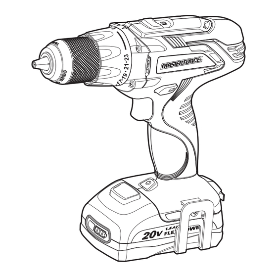
OVERVIEW FIG. 1 Two-Speed Torque-Adjustment ring Gearbox Switch Direction-of- Rotation Selector Keyless chuck Trigger switch LED Worklight Battery-release button Belt clip SPECIFICATIONS Motor Chuck 1/2” No-load Speed 0-450/0-1600 RPM Max . Torque 455 in .lbs Clutch 23+1 Position Weight (without battery) 2 lb . -
Page 9: Assembly
ASSEMbLy UNPACkING WARNING: If any part is broken or missing, DO NOT attempt to attach the 1 . This product been shipped battery or operate the tool until the broken completely assembled . or missing part is replaced. Failure to do 2 . -
Page 10: Operation
OPERATION TO ATTACH bATTERy PACk 3 . Pull forward on the battery pack to remove it from the drill/driver . (FIG. 2) FIG. 2 TRIGGER SWITCH (FIG. 3) FIG. 3 ATTACH Direction- DETACH of-Rotation Variable Selector Speed Trigger CAUTION: Switch Avoid the possibility of accidental starting . - Page 11 OPERATION ELECTRIC bRAkE The direction of rotation of the bit is reversible and is controlled with a selector located above the trigger switch . With the To stop the tool, release the trigger switch drill/driver held in normal operating position: and allow the chuck to come to a complete Position the direction-of-rotation selector to stop .
- Page 12 OPERATION kEyLESS CHUCk (FIG. 7) TWO-SPEED GEAR bOX (FIG. 9) FIG. 7 Release FIG. 9 Slide Switch Keyless Chuck Grip The arrows on the chuck indicate the This drill/driver features two-speed direction of rotation of the body of the chuck gearbox that is designed for drilling or to: GRIP (tighten) or OPEN (release) the jaws driving at LO speed or HI speed .
- Page 13 OPERATION INSTALLING A bIT (FIG. 11) ADJUSTAbLE TORQUE CLUTCH (FIG. 10) FIG.11 Release FIG.10 Arrow Keyless Chuck Grip Torque-Adjustment ring 1 . Lock the trigger switch by placing the direction-of-rotation selector in the OFF The torque clutch can be adjusted to any (centre) position .
- Page 14 OPERATION REMOVING A bIT (FIG. 11a) 1 . Check the direction-of-rotation selector for the correct setting (forward or FIG.11a reverse) . 2 . Use a vise or clamps to secure the material to be drilled to keep it from turning as the drill bit rotates . 3 .
- Page 15 OPERATION DRILLING MODE OPERATION SCREWDRIVER OPERATION For drilling in wood, use twist bits, spade 1 . Select the desired speed/torque range bits, power auger bits or hole saws . to match the planned operation . 2 . Attach the desired fastener accessory 1 .
-
Page 16: Maintenance
MAINTENANCE Periodic maintenance of your shear allows WARNING: To avoid serious for long life and trouble-free operation. personal injury, always disconnect A cleaning, lubrication and maintenance the plug from the power source when schedule should be maintained. cleaning or performing any maintenance. Contact a qualified service technician for As a common-sense and preventive ALL repairs. -
Page 17: Troubleshooting
TROUbLESHOOTING PRObLEM CAUSE SOLUTION The drill/driver does not work Battery is depleted Charge the battery Chuck is not opened Open the chuck Bit cannot be installed Bit does not fit the chuck Use suitable bit Clean, clear vents . Do not Be sure cooling vents are Motor overheating cover with hand during... - Page 18 NOTES Page 17...
-
Page 19: Warranty
High-Performance 1/2” Drill/Driver WARRANTy 90-DAy MONEy bACk GUARANTEE: This MASTERFORCE® brand power tool carries our 90-DAY Money Back Guarantee . If you are not completely satisfied with your MASTERFORCE® brand power tool for any reason within ninety (90) days from the date of purchase, return the tool with your original receipt to any MENARDS®... - Page 20 © 2012 Menard, Inc ., Eau Claire, WI 54703 07/2012...
Need help?
Do you have a question about the 241-0405 and is the answer not in the manual?
Questions and answers