Advertisement
Operator's Manual
18.0-Volt Lithium-Ion Drill/Driver
Model No. 241-0420
IMPORTANT :
WARNING! To reduce the risk of injury, user must read instruction
manual.
Safety symbols in this manual are used to flag possible dangers. The safety
symbols and their explanations require your full understanding. The safety
warnings do not, by themselves, eliminate any danger, nor are they substitute
for proper accident prevention measures.
This Safety Alert Symbol indicates caution, warning, or danger. Failure to
obey a safety warning can result in serious injury to yourself or others. To reduce
the risk of injury, fire, or electric shock, always follow the safety precautions. .
CHARGE BATTERY
BEFORE FIRST USE
Advertisement

Related Manuals for Master-force 241-0420


Summary of Contents for Master-force 241-0420
- Page 1 Operator’s Manual 18.0-Volt Lithium-Ion Drill/Driver Model No. 241-0420 CHARGE BATTERY BEFORE FIRST USE IMPORTANT : WARNING! To reduce the risk of injury, user must read instruction manual. Safety symbols in this manual are used to flag possible dangers. The safety symbols and their explanations require your full understanding.
-
Page 2: Table Of Contents
TABLE OF CONTENTS Safety Symbols ....................page 3 Safety Instructions ..................page 5 Description .....................page 10 Assembly ......................page 11 Operation ......................page 12 Maintenance ....................page 22 Troubleshooting .....................page 24 Warranty ......................page 24 INTRODUCTION SAVE THESE INSTRUCTIONS! This cordless Drill Driver has many features for making its use more pleasant and enjoyable. -
Page 3: Safety Symbols
SAFETY SYMBOLS The purpose of safety symbols is to attract your attention to possible dangers. The safety symbols and the explanations with them deserve your careful attention and understanding. The symbol warnings do not, by themselves, eliminate any danger. The instructions and warnings they give are no substitutes for proper accident prevention measures. - Page 4 SAVE THESE INSTRUCTIONS Some of these following symbols may be used on this tool. Please study them and learn their meaning. Proper interpretation of these symbols will allow you to operate the tool better and safer. Volts Voltage Amperes Current Hertz Frequency (cycles per second) Watt...
-
Page 5: Safety Instructions
SAFETY INSTRUCTIONS GENRAL SAFETY RULES WARNING! Read all safety warnings and instructions. Failure to follow the warnings and instructions may result in electric shock, fire and / or serious injury. Save all warnings and instructions for future reference. The term power tool in the warnings refers to your mains-operated (corded) power tool or battery-operated (cordless) power tool. - Page 6 PERSONAL SAFETY Stay alert, watch what you are doing and use common sense when operating a power tool. Do not use tool while tired or under the influence of drugs, alcohol, or medication. A moment of inattention while operating power tools may result in serious personal injury. Use personal protective equipment.
- Page 7 power tool’s operation. If damaged, have the power tool repaired before use. Many accidents are caused by poorly maintained power tools. keep cutting tools sharp and clean. Properly maintained cutting tools with sharp cutting edges are less likely to bind and are easier to control. Use the power tool, accessories and tool bits etc., in accordance with these instructions, taking into account the working conditions and the work to be performed.
- Page 8 the clamp to cool down. The bit may be hot after prolonged use. Use protective gloves when operating the tool. Protective gloves can help to keep you from being burnt and hurt. Keep your hands away from the motor-housing vents. Hot gas comes from the vents during operation.
- Page 9 internal parts. Do not allow gasoline, oils, petroleum-based products, etc. to come in contact with plastic parts. These materials contain chemicals that can damage, weaken, or destroy plastic. An extension cord should not be used unless absolutely necessary. Use of an improper extension cord could result in a risk of fire and electric shock.
-
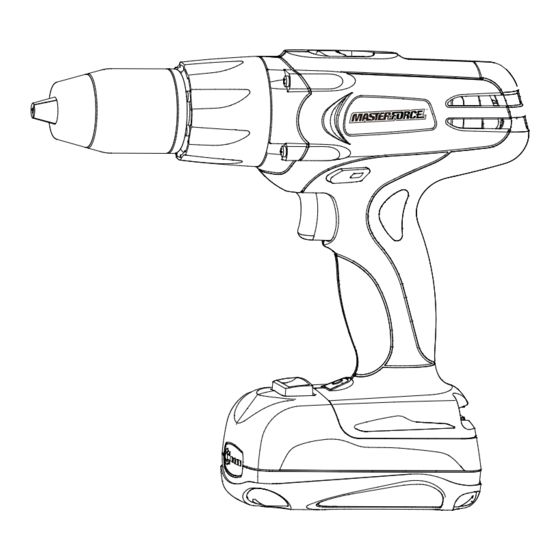
Page 10: Description
DESCRIPTION kNOW YOUR DRILL/DRIVER (Fig.1) Torque adjustment ring Fig. 1 Two-speed gearbox switch Keyless chuck Vents Variable-speed Direction of Rotation trigger switch Selector (Forward/ Center Lock/ Reverse) LED Worklight Battery Release Button Powerdisplay button Battery Pack Power display PRODUCT SPECIFICATIONS Motor 18Volt DC Switch... -
Page 11: Assembly
WARNING! The safe use of this product requires an understanding of the information on the tool and in this operator’s manual, as well as knowledge of the project you are attempting. Before use of this product, familiarize yourself with all operating features and safety rules. ADJUSTABLE TORQUE The drill/driver has 23 driving and 1 drilling positions TWO-SPEED GEAR BOX... -
Page 12: Operation
UNPACkING This product has been shipped completely assembled. Carefully remove the tool and any accessories from the box. Make sure that all items listed in the packing list are included. Inspect the tool carefully to make sure no breakage or damage occurred during shipping. - Page 13 its run time and needs to be charged, power to the tool will drop quickly. The power indicator will begin to display four flashing LED lights when it is completely discharged. When this happens, remove the tool from the workpiece and charge the battery pack as needed. BATTERY PROTECTION To protect the battery from damage and prolong its life, the battery pack circuitry will turn off the battery pack if it becomes overloaded or if the...
- Page 14 HOW TO CHARGE THE BATTERY PACk NOTE: This Lithium-Ion battery pack is shipped partially charged. Before using it the first time, fully charge the battery pack. A fully discharged battery pack will charge in about 45 minutes (for included battery pack 252-8028) in a surrounding temperature between 41° F (5° C) and 122°...
- Page 15 CHARGING A HOT BATTERY PACk If the battery pack is above normal temperature range, the red LED will illuminate and the green LED will be off. When the battery pack cools down to approximately 122°F (50°C), the charger will automatically begin charging. CHARGING A COLD BATTERY PACk If the battery pack is below the normal temperature range, the red LED will illuminate and the green LED will be off.
- Page 16 TO ATTACH BATTERY PACk (Fig. 5) Fig. 5 1. Lock the trigger switch on the drill/driver by placing the direction of rotation (forward/ reverse/center lock) selector in center (locked) position ATTACH 2. Align the raised portion on the battery pack with the grooves on the bottom of the drill/driver, and then attach the battery pack to the drill as shown.
- Page 17 DIRECTION-OF-ROTATION SELECTOR (FORWARD/REVERSE/CENTER LOCk) (Fig. 6b) Fig. 6b The direction of bit rotation is reversible and is controlled by a selector located above the trigger switch. With the Drill/Driver held in FORWARD REVERSE normal operating position: 1. Position the direction-of-rotation selector to the left of the tool for forward rotation.
- Page 18 TWO-SPEED GEAR BOX (Fig. 8) Fig. 8 The drill/driver has a two-speed gear box designed for drilling or driving at LO or HI speeds. A slide switch is located on the top of the drill/driver to select either LO or HI speed.
- Page 19 material you will be using. In general, use greater torque for larger screws, but if the torque is too high, the screws may be damaged or broken. For delicate operations, such as removing a partially stripped screw, use a low torque setting. For operations such as drilling into hardwood, use a higher torque setting.
- Page 20 to close the chuck jaws. Do not use a wrench to tighten or loosen the chuck jaws. 4. Tighten the chuck jaws securely on the bit. REMOVING BITS (Fig. 12) WRONG! 1. Lock the trigger switch by Fig. 12b placing the direction of rotation selector in the OFF (center) position.
- Page 21 9. If the bit jams in the workpiece or if the drill stalls, stop the tool immediately. Remove the bit from the workpiece and determine the reason for jamming. WARNING! This drill/driver is equipped with an electric brake. When the brake is functioning properly, sparks may be visible through the vent slots in the housing.
-
Page 22: Maintenance
- Overheat the drill/driver. - Wear the bearings. - Bend or burn bits. - Produce off-center or irregular-shaped holes. 3. Apply light pressure and medium speed for best results in brick. 4. Apply additional pressure for hard materials such as concrete. 5. - Page 23 especially when wearing rings and jewelry, could result in a serious burn. To obtain the longest possible battery life, read and understand the operator’s manual. It is good practice to unplug the Charger/Adapter and remove the Lithium- Ion battery pack when not in use. For Lithium-Ion battery pack storage longer than 30 days: Store the Lithium-Ion battery pack where the temperature is below 80°F (26°C) and free of moisture.
-
Page 24: Troubleshooting
tighten the chuck jaws securely. 4. Tap the hex key sharply with a mallet in anti-clockwise direction. This will loosen the chuck for easy removal. 5. Attach a new chuck to the spindle and tighten the chuck screw. TROUBLESHOOTING PROBLEM CAUSE SOLUTION The drill/driver does not...
Need help?
Do you have a question about the 241-0420 and is the answer not in the manual?
Questions and answers