GE Monogram ZGU375NS Technical Service Manual
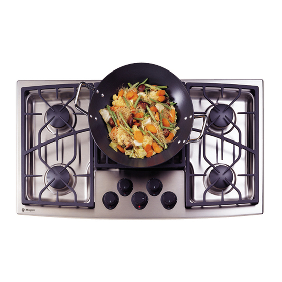
36-in. stainless steel gas cooktop
Hide thumbs
Also See for Monogram ZGU375NS:
- Owner's manual (20 pages) ,
- Installation instructions manual (12 pages) ,
- Technical service manual (32 pages)

Related Manuals for GE Monogram ZGU375NS


Summary of Contents for GE Monogram ZGU375NS
- Page 1 GE Consumer Home Services Training TECHNICAL SERVICE GUIDE 36-In. Monogram Stainless Steel Gas Cooktop MODEL SERIES: ZGU375NS ZGU375LS PUB # 31-9088 12/01...
- Page 2 If grounding wires, screws, straps, clips, nuts, or washers used to complete a path to ground are removed for service, they must be returned to their original position and properly fastened. GE Consumer Home Services Training Technical Service Guide Copyright © 2001 All rights reserved.
-
Page 3: Table Of Contents
Table of Contents Table of Contents Introduction ........... . . 2 Installation . -
Page 4: Introduction
Introduction The new Monogram cooktop makes an eloquent This Monogram cooktop was designed to provide statement of style, convenience, and kitchen the flexibility to blend in with any kitchen cabinetry. planning flexibility. Whether chosen for its purity of Its sleek design can be beautifully integrated into design, assiduous attention to detail—or for both of the kitchen. -
Page 5: Installation
Gas Supply Shutoff Valve Gas Supply The cooktop itself is not equipped with a gas shut- WARNING: Cooktop model ZGU375NS is shipped off valve. If installed correctly, a shutoff valve will be from the factory set to operate only with natural in the main gas supply line “upstream”... -
Page 6: Specifications And Nomenclature5
Specifications and Nomenclature Model Number Z G U 3 7 5 N S Monogram Stainless Steel Type of Gas to Be Used N = Natural L = LPG Cooktop Feature Pack Designates features–the higher the number, the more features. Serial Number The first two characters of the serial number identify the month and year of manufacture. -
Page 7: Warranty Information
Warranty Information Sales slip or cancelled check is required as proof of original purchase date to obtain service under warranty. All warranty service is provided by our Factory Service Centers or an authorized Customer Care ® technician. What is FULL ONE-YEAR WARRANTY Covered For one year from date of original purchase, we will provide, free of charge, parts and service labor in your home to repair or replace any part of the cooktop that fails because... -
Page 8: Cooktop Features And Controls
Cooktop Features and Controls Throughout this manual, features and appearances may vary from the customer’s model. Design information (Not all features are on all models. Appearance may vary.) Feature Index Dual-Flame Spillproof Burners—High Output Dual-Flame Spillproof Burner—Maximum Output Tactile-touch Control Knobs (One for Each Surface Burner) Burner “ON”... - Page 9 Burner Cleaning The slits in the burner rings of the cooktop must be kept clean at all times for an even, unhampered flame. Electrode The electrode of the spark igniter is Check to be sure the burner you turned on is behind each burner.
- Page 10 Burner Cap Burner Cap Burner Head Burner Head (Brass) (Brass) Burner Ring Burner Ring Locking Nut Locking Nut Locator Pin Locator Pin Burner Ring Burner Ring (Aluminum) (Aluminum) Electrode Electrode Locator Pin Locator Pin Burner Base Burner Base Slot Slot NOTE: Locator pin fits NOTE: Locator pin fits into burner base pin slot.
- Page 11 Cooktop Cleaning Stainless Steel: This metal alone has poor heating properties and is usually combined with If cooktop has discolored from high heat, advise copper, aluminum, or other metals for improved customer to use the furnished cleaner (WB64X93) heat distribution. Combination metal skillets identified in Owner’s Manual.
-
Page 12: Mechanical Disassembly
Mechanical Disassembly Table of Contents Maintop Removal ..........11 Spark Module Removal . -
Page 13: Maintop Removal
Caution: When removing the wire from the igniter, WARNING: Disconnect electrical power to the make sure you do not damage the heat shrink cooktop and turn OFF gas at the main valve before insulation on the wire. If damaged, repair the wire performing any removal procedures. -
Page 14: Spark Module Removal
6. Remove the left screws holding the bezels for Heat Shield the left-front and right-front gas valve knobs. Remove Screws 11. To reinstall the maintop, reverse the procedure 1 through 10. 7. Raise the maintop front about 6 in. and discon- Spark Module Removal nect the 6-pin connector under the maintop and behind the right-front valve. -
Page 15: Transformer Removal
Transformer Removal 5. Lift each igniter switch off the valve stem. 1. Remove the maintop (see Maintop Removal 2. Remove the heat shield held by 4 Phillips screws. Note: Note the color and position of the 4 transformer wires. 3. Remove 3 wire screw connectors and 1 ground connector screw. -
Page 16: Manifold Removal
6. From under the counter, remove 2 screws at 5. Remove the 9/16-in. nut on the gas line to the the manifold. main jet holder and remove the gas line. 7. Remove two 7/16-in. screws and the manifold. 6. Remove two 5/16-in. nuts and the valve. 7. -
Page 17: Main Jet Holder Removal
Main Jet Holder Removal Center Brace Removal 1. Remove the maintop (see 1. Remove the maintop (see Maintop Removal Maintop Removal 2. Remove the 9/16-in. nut on the gas line. 2. Remove the simmer jet holders (see Simmer Jet Holder Removal 3. -
Page 18: Troubleshooting
Troubleshooting Problem Possible Causes What to Do Incorrect gas being used. • Check for correct gas supply Burner flames are very large, yellow, The combustion quality • Use the illustrations below to determine if the burner or yellow-tipped of burner flames needs flames are normal. - Page 19 Problem Possible Causes What to Do Improper flame sensing. • Check igniter wiring. Ticking sound of • Replace the igniter. spark igniter persists after burner lights Be sure the knob is in • Remove knob and check the bottom of knob for buildup Ticking sound the OFF position.
-
Page 20: Component And Connector Locator Views
Component and Connector Locator Views Note: Also see for additional components. Parts List Transformer Spark Module Heat Shield (Remove to access Spark Module & Brace Brace Igniter Transformer) Wire Igniter Switch Valve Manifold 6-Pin Plug Burner Lights (on under side of top) –... - Page 21 Notes – 19 –...
-
Page 22: Wiring Diagram
Wiring Diagram CONNECTOR POWER CORD 5 POINT WN #2 GAS RE-IGNITER WN #3 MODULE 230V 120V SPARK ELECTRODES 120/230V ON BURNERS TRANSFORMER (RR) 230V (LR) WN #1 (LF) (RF) RR VALVE SW. LR VALVE SW. RF VALVE SW. CENTER VALVE SW. LF VALVE SW. -
Page 23: Schematics
120/230V TRANSFORMER 5 POINT GAS RE-IGNITER MODULE 120V 230V ELECTRODES POWER CORD 120 VAC IN VALVE INDICATOR SWITCHES LIGHTS Caution: Label all wires prior to disconnection when servicing the controls. Wiring errors can cause improper and dangerous operation. Verify proper operation after servicing. -
Page 24: Parts List
Parts List Note: The components shown in this drawing may differ from the components in your unit. Refer to the microfiche or GEA IPC for the component and part number for your unit. – 22 –... - Page 25 Screw 47, 50 Note: The components shown in this drawing may differ from the components in your unit. Refer to the microfiche or GEA IPC for the component and part number for your unit. – 23 –...
- Page 26 8, 9, 10, 13, 14 11, 12 22, 23, 24, 25, 26 8, 9, 10, 13, 14 22, 23, 24, 25, 26 11, 12 8, 9, 10, 13, 14 Note: The components shown in this drawing may differ from the components in your unit.
- Page 27 Note: The components listed below may differ from the components in your unit. Refer to the microfiche or GEA IPC for the component and part number for your unit. Views Description Part No. C SIMMER/ PORT RING ASSY WB32X10026 D SIMMER/ PORT RING ASSY WB32X10027 C BURNER BASE ASSY WB28X10044...
-
Page 28: Conversion To/From Lp (Propane) Gas
Conversion to/from LP (Propane) Gas Before you begin, read these instructions completely and carefully TOOLS NEEDED PARTS INCLUDED WARNING 1/8" Flat-blade Screwdriver Main Burner Orifice (5) Adjustable Wrench Simmer Burner Orifice (5) This conversion kit must be installed by a qualified service Phillips Screwdriver Valve Orifice (5) agency in accordance with the manufacturer’s instructions... - Page 29 STEP 2 7. Raise the cooktop front about 6" and disconnect the 6 pin connector under the cooktop and behind the right front Replace All Burner and Valve Orifices valve. 8. Push the spark electrode wire through the holes in the cooktop.
- Page 30 STEP 3 Convert the Pressure Regulator Reverse Plastic Plunger WARNING Do not remove the pressure regulator from the cooktop. To convert the regulator from Natural Gas to LP gas or LP to Natural, remove the cap screw using an adjustable wrench and reverse the plastic plunger (make sure the plunger is firmly “swapped”...
- Page 31 STEP 6 (continued) Burner Cap Burner Operation Two flames are used on all five burners. These dual flame burners have an High to Low upper ring of main burner ports which produce the main flame for high heat Flame cooking from the “HI” knob setting to the “LO” knob setting. Simmer Flame The bottom simmer flame is used for simmer heat cooking operations such as melting chocolate, holding food at serving temperature and simmering.
- Page 32 – 30 –...
Need help?
Do you have a question about the Monogram ZGU375NS and is the answer not in the manual?
Questions and answers