Table of Contents
Advertisement
Advertisement
Table of Contents

Subscribe to Our Youtube Channel
Related Manuals for Velleman K8055N


Summary of Contents for Velleman K8055N
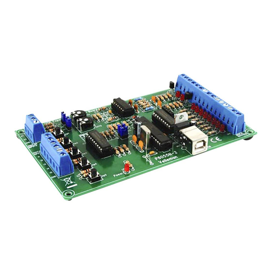
- Page 1 Total solder points: 313 Difficulty level: beginner 1 2 3 4 5 advanced USB Experiment interface board K8055N Interface your computer with the world using 5 digital in– and 8 outputs, 2 analogue in-and outputs.
- Page 2 General - Algemeen - En général - Allgemein - Generalidades UK See the product page on our website for the latest available software & manual translation NL Download de laatst beschikbare software en vertaalde handleiding op de productpagina van onze website. FR Consultez la fiche technique sur notre site web pour la toute dernière version de logiciel et la traduction du mode d'emploi.
- Page 3 Features Minimum system requirements: 1 GHz or faster 32-bit (x86) or 64-bit (x64) processor USB1.1 or higher connection Windows XP or later Specifications 5 digital inputs (0= ground, 1= open) (on board test buttons provided) 2 analogue inputs with attenuation and amplification option (internal test +5V provided) ...
- Page 4 Assembly hints 1. Assembly (Skipping this can lead to troubles ! ) Ok, so we have your attention. These hints will help you to make this project successful. Read them carefully. 1.1 Make sure you have the right tools: A good quality soldering iron (25-40W) with a small tip. ...
- Page 5 REMOVE THEM FROM THE TAPE ONE AT A TIME ! DO NOT BLINDLY FOLLOW THE ORDER OF THE COMPONENTS ONTO THE TAPE. ALWAYS CHECK THEIR VALUE ON THE PARTS LIST!
- Page 6 Construction 1. Jumper R3 : 680 (6 - 8 - 1 - B) R31 : 10K (1 - 0 - 3 - B) R4 : 680 (6 - 8 - 1 - B) R32 : 10K (1 - 0 - 3 - B) ...
-
Page 7: Ceramic Capacitors
Construction 6. LED’s. Watch the polarity! 8. IC sockets. Watch the 4. Ceramic Capacitors position of the notch! LD1 LD2 LD3 LD4 CATHODE IC1 : 14P LD5 IC2 : 18P LD6 3mm RED IC3 : 28P ... -
Page 8: Screw Connectors
Construction 11. Header 14. Quartz crystal 16. Voltage regulator VR1 : LM317 X... SK2 : 2P X1 : 4MHz SK3 : 2P SK5 : 2P SK6 : 2P 15. Screw connectors SK1 : 3P 17. -
Page 9: Rubber Feet
Construction 18. GAIN FACTOR The analogue inputs A1 and A2 have a standard range of 0 ~ +5Vdc. To use them externally, remove the jumper caps on SK2 and SK3. The internal 5V voltage source can only be used for testing purposes. When the input voltage is too low you can amplify it x4 / x15. -
Page 10: Connection Settings
Connection / settings 20. Connection / settings Internal / external voltage Analog signal adjust Address selection DC voltage 5 ... 30V Test LEDs Test buttons If the jumper is mounted, then you can use the internal voltage and adjust it using RV2/RV1. If the jumper is not mounted you must use the external voltage A2/A1. -
Page 11: Test Procedure
Connection / settings Select the correct address in the test program DIGITAL OUTPUTS : 8 open collector contacts, to be connected with suitable inputs. These exits function as ‘dry contact points’: you need an external voltage to control a component such as a LED or a relay switch. - Page 12 Test procedure The message "Card x connected" is displayed if the connection is successful You can now simulate the inputs via push buttons Inp1 through Inp5. The matching check box remains ticked off as long as you keep one of the push buttons pressed down. Always tick off the check box for the matching output if you wish to test a digital output.
-
Page 13: Connection Scheme
Connection scheme 22. Connection Scheme Analog voltage 0 ...5V Analog input example PWM output example Digital input example Digital output example... - Page 14 23. PCB...
- Page 15 Schematic diagram 24. Schematic diagram.
- Page 16 VELLEMAN NV Legen Heirweg 33, B-9890 GAVERE Belgium (Europe) Modifications and typographical errors reserved © Velleman nv. H8055NIP - 2013 - ED1 (rev.1)
Need help?
Do you have a question about the K8055N and is the answer not in the manual?
Questions and answers