Advertisement
Quick Links
Advertisement

Related Manuals for Velleman K8042


Summary of Contents for Velleman K8042
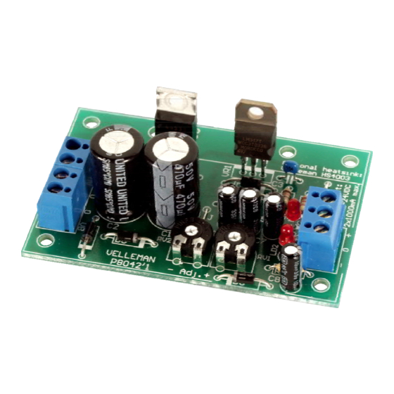
- Page 1 SYMMETRIC 1A POWER SUPPLY K8042 ILLUSTRATED ASSEMBLY MANUAL H8042IP-1...
-
Page 2: Specifications
Features & Specifications Features low cost universal symmetric power supply just add a suitable transformer and a heatsink ideal for e.g. op-amp applications, amplifiers, ... trimmers can be replaced by potmeters to allow continuous adjustment of output voltage ... -
Page 3: Assembly Hints
Assembly hints 1. Assembly (Skipping this can lead to troubles ! ) Ok, so we have your attention. These hints will help you to make this project successful. Read them carefully. 1.1 Make sure you have the right tools: A good quality soldering iron (25-40W) with a small tip. - Page 4 3- Trim excess leads as close as possible to the solder joint AXIAL COMPONENTS ARE TAPED IN THE CORRECT MOUNTING SEQUENCE ! REMOVE THEM FROM THE TAPE ONE AT A TIME ! You will find the colour code for the resistances and the LEDs on our website: http://www.velleman.be/common/service.aspx...
- Page 5 Construction 1. Jump wire 4. Capacitors. 7. LEDs. Watch the polarity! J C3 : 100nF (104) C... C4 : 100nF (104) 2. Diodes. Watch the polarity ! 23mm 10mm LD... 0.9" D1 : 1N4007 5. Trim potentiometers ...
-
Page 6: Voltage Regulators
Construction 9. Voltage regulators VR1 : LM317 VR2 : LM337 VR... 10. Heatsink 15mm M3 bolt When you want to use the maximal 20W dissipation mount the optional heat sink, ordernr. : HS4003. Apply a little heat conducting paste (obtain from your specialized dealer) to one side of an insulation plate and press it with this side against the heatsink, there were the component has to be fitted. - Page 7 Heatsink construction Fit the components and heatsink onto the PCB and fix it by means of two 5mm spacers and two screws. Spacer Screw Solder now the connections of the voltage regulators.
- Page 8 Enclosure 11. Using a metal enclosure as a heatsink When mounting the Kit into a enclosure, you have to drill two holes in the backside of the housing to pass the 15mm M3 bolts trough. Heat conducting paste 15mm M3 bolt M3 nut Insulation plate Insulation tube...
- Page 9 enclosure 12. Connection Req. output Req. AC input voltage voltage (transformer) +/- 1,2 ... 5V 2 x 9VAC +/- 5 ... 9V 2 x 12 - 15VAC +/- 9 ... 12V 2 x 15VAC +/- 12 ... 15V 2 x 18VAC +/- 15 ...
- Page 10 13. PCB layout...
- Page 11 diagram 14. Diagram...
- Page 12 VELLEMAN NV Legen Heirweg 33, B-9890 GAVERE Belgium (Europe) Modifications and typographical errors reserved © Velleman nv. H8042IP’1 - 2014 (rev.2) 5 4 1 0 3 2 9 3 2 7 1 3 2...
Need help?
Do you have a question about the K8042 and is the answer not in the manual?
Questions and answers