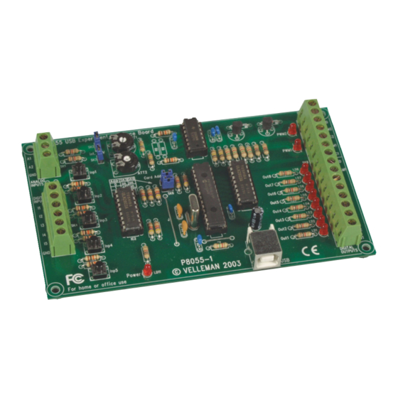
Summary of Contents for Velleman VM110
- Page 1 USB EXPERIMENT INTERFACE BOARD VM110 Belgium [Head office] +32(0)9 384 36 11 France +33(0)3 20 15 86 15 Netherlands +31(0)76 514 7563 +1(817)284-7785 Spain +32(0)9 384 36 11...
- Page 2 Vertaling van deze handleiding, alsook meer gegevens van deze module kan men terugvinden op de CD. Vous trouverez la traduction de cette notice sur le CD, avec d'autres informations/données. Svensk Bruksanvisning och annan information finns på medföl jande CD. Tämän käyttöohjeen sekä muun informaation suomenkielinen käännös on oheisella CD:llä. La traduzione di questo manuale e tutte le informazioni concernenti l'unità...
-
Page 3: Table Of Contents
This product is guaranteed against defects in components and construction from the moment it is purchased and for a period of ONE YEAR starting from the date of sale. This guarantee is only valid if the unit is submitted together with the original purchase invoice. VELLEMAN Ltd limits its responsibility to the reparation of defects or, as VELLEMAN Ltd deems necessary, to the replacement or reparation of defective components. -
Page 4: Specifications & Features
Specifications & features Specifications and features SPECIFICATIONS* 5 Digital inputs (0= ground, 1= open). On board test buttons provided. 2 Analog inputs (0 …+5V) with attenuation and amplification option. Internal test +5V provided. 8 Digital open collector output switches (max 50V/100mA). On board LED indication. 2 Analog outputs 0 to 5V, output resistance 1K5. -
Page 5: Demo Software
1. Run setup.exe from the directory 'K8055_VM110 USB board/Demo PC soft install' If the CD starts up automatically : 1. Choose "Browse this CD for other velleman software' 2. Run setup.exe from the directory 'K8055_VM110 USB board/Demo PC soft install' An installation wizard will guide you trough the installation •... -
Page 6: Control & Indicators
Control & indicators Control & indications 5 digital inputs (e.g. push button, switch, relay contact, ...). Input is generally "high" (1), connection to GND makes the input "low" (0). Analogue inputs (e.g. temperature sensor, potentiometer, ...) 0 ... +5VDC MAX! If the jumper is mounted, then you can use the internal voltage and adjust it using RV2/RV1. - Page 7 Control & indicators...
-
Page 8: Connection Diagram
RVx : FOR EXPERIMENTAL USE mount SK2 & SK3 when using RV1,2 "1" "0" To external electronics analog output 0 ... 5V 220V P8055-1 VELLEMAN 2003 EXTERNAL ! DC voltage 5 ... 30V DC Adapter (ex. PS1208) From PC USB1.X... - Page 9 Warnings WARNING UK : PLEASE NOTE THAT THE GROUND OF THE BOARD IS NOT ISOLATED FROM THE COMPUTER GROUND! ND : DE MASSA VAN HET BORD IS NIET GESCHEIDEN MET DE COMPUTERMASSA! FR : REMARQUEZ QUE LA TERRE DE LA PLAQUE N'EST PAS ISOLEE DE LA TERRE DE L'ORDINATEUR ! : BITTE VERGEWISSEM SIE SICH, DASS SICH DIE ERDUNG DER PLATINE UND DIE ERDUNG DES COMPUTERS NICHT GEGENSEITIG ISOLIERT SIND!
-
Page 10: Test Procedure
Test procedure Test procedure The included demo software makes it easy to experiment. Start by selecting the address : tick off SK5 and/or SK6 (see address selection). ADDRESS ATTENTION : Execute these settings before connecting the kit with the computer or before booting the computer. Connect the USB cable. - Page 11 Test procedure You can now simulate the inputs via push buttons Inp1 through Inp5. The matching check box remains ticked off as long as you keep one of the push buttons pressed down. Always tick off the check box for the matching output if you wish to test a digital output. You can also conduct this procedure automatically : press the 'output test' button or activate all outputs with the 'Set all digital' button.
- Page 12 Modifications and typographical errors reserved - © Velleman nv. HVM110G - 2004 - ED1 (Rev 3.0) 5 4 1 0 3 2 9 3 0 5 8 1 9...


Need help?
Do you have a question about the VM110 and is the answer not in the manual?
Questions and answers