Table of Contents
Advertisement
NOTE:
Please read all instructions
carefully before using this
product
Table of Contents
IRON GRIP STRENGTH
Safety Notice
Standard Bench
Hardware Identifier
IGS-5683
Assembly Instruction
Parts List
Warranty
Ordering Parts
Model
IGS-5683
Retain This
Manual for
Reference
07-14-06
OWNER'S
MANUAL
®
IMPEX
INC.
14777 DON JULIAN RD., CITY OF INDUSTRY, CA 91746
Tel: (800) 999-8899 Fax: (626) 961-9966
www.impex-fitness.com
info@impex-fitness.com
Advertisement
Table of Contents

Related Manuals for Impex Iron Grip Strength IGS-5683


Summary of Contents for Impex Iron Grip Strength IGS-5683
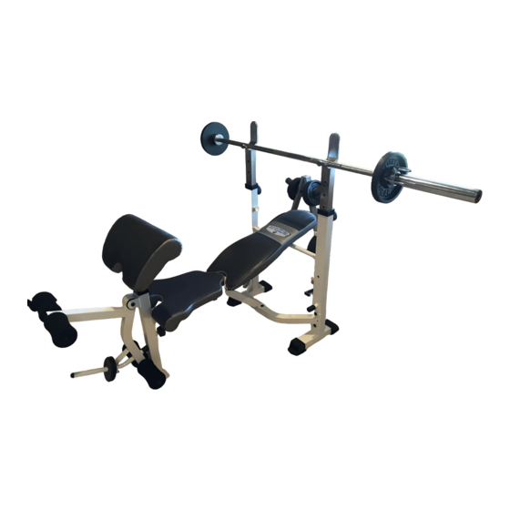
- Page 1 NOTE: Please read all instructions carefully before using this product Table of Contents IRON GRIP STRENGTH Safety Notice Standard Bench Hardware Identifier IGS-5683 Assembly Instruction Parts List Warranty Ordering Parts Model IGS-5683 Retain This Manual for Reference 07-14-06 OWNER'S MANUAL ®...
-
Page 2: Table Of Contents
BEFORE YOU BEGIN Thank you for selecting the IRON GRIP STRENGTH Standard Bench IGS- ® 5683 by IMPEX INC. For your safety and benefit, read this manual carefully before using the machine. you complete customer satisfaction. If you have any questions, or find there are missing or damaged parts, we guarantee you complete satisfaction through direct assistance from our factory. -
Page 3: Care And Maintenance
PHYSICIAN. THIS IS ESPECIALLY IMPORTANT FOR INDIVIDUALS OVER THE AGE OF 35 OR PERSONS WITH PRE-EXISTING HEALTH PROBLEMS. READ ALL INSTRUCTIONS BEFORE USING ANY FITNESS EQUIPMENT. IMPEX INC. ASSUMES NO RESPONSIBILITY FOR PERSONAL INJURY OR PROPERTY DAMAGE SUSTAINED BY OR THROUGH THE USE OF THIS PRODUCT. -
Page 4: Warning Label Placement
WARNING LABEL PLACEMENT The Warning Label shown here has been placed on the Cross Brace. If the label is missing or illegible, please call customer service at 1-800-999-8899 for replacement. Apply the label in location shown. -
Page 5: Hardware Pack
HARDWARE PACK... - Page 6 HARDWARE PACK...
-
Page 7: Assembly Instruction
ASSEMBLY INSTRUCTION Tools Required Assembling the Machine: Two Adjustable Wrenches and Allen Wrenches. NOTE: It is strongly recommended two or more people assembling this machine to avoid possible injury. STEP 1 (See Diagram 1) A.) Connect the Left & Right Upright Beams (#1 & 2) by a Cross Brace (#3) in the mid-span. Align the holes and secure each end of the Cross Brace with one 4 ¾”... - Page 8 STEP 2 (See Diagram 2) A.) Attach Main Seat Support (#4) to the Cross Brace (#3). Secure it with a 4 3/8” x 1 ¾” Bracket (#19), two M10 x 2 ½” Carriage Bolts (#42), two M10 Aircraft Nuts (#50). B.) Attach the Leg Developer Holder (#5) to the Main Seat Support (#4).
- Page 9 STEP 3 (See Diagram 3) A.) Attach the Leg Developer (#11) to the Leg Developer Holder (#5). Secure it with an Axle (#54), two M10 x 5/8” Allen Bolts (#47), and two B.) Insert two Foam Tubes (#14) halfway through the holes on the Leg Developer. Push four 4”...
- Page 10 A.) Attach the two side-holes on the two Backrest Supports (#13) to the pivot on the Main Seat Support (#4). Align the holes and secure it with one M12 x 7 ¼” Hex Bolt (#44), 1” Washers (#40), and one M12 Aircraft Nut (#51). B.) Place the Backrest Board (#16) onto the Backrest Supports.
-
Page 12: Parts List
PARTS LIST KEY NO. DESCRIPTION Left Upright Beam Right Upright Beam Cross Brace Main Seat Support Leg Developer Holder Seat Bracket Crutch Backrest Adjustment Bar Left Butterfly Right Butterfly Leg Developer Arm Curl Stand Backrest Support Foam Tube Butterfly Handle Backrest Board Seat Arm Curl Pad... -
Page 13: Limited Warranty
IMPEX. IMPEX is not responsible or liable for indirect, special or consequential damages arising out of or in connection with the use or performance of the product or other damages with respect to any economic loss, loss of property, loss of revenues or profits, loss of enjoyments or use, costs of removal, installation or other consequential damages or whatsoever natures.
Need help?
Do you have a question about the Iron Grip Strength IGS-5683 and is the answer not in the manual?
Questions and answers