Table of Contents
Advertisement
Quick Links
NOTE:
Please read all instructions
carefully before using this
product
Table of Contents
Safety Notice
Hardware Identifier
Assembly Instruction
Parts List
Warranty
Ordering Parts
Model
IGS-6500
Retain This
Manual for
Reference
11-26-07
OWNER'S
MANUAL
IRON GRIP STRENGTH
POWER SYSTEM
14777 DON JULIAN RD., CITY OF INDUSTRY, CA 91746
Tel: (800) 999-8899 Fax: (626) 961-9966
www.impex-fitness.com
info@impex-fitness.com
IGS-6500
®
IMPEX
INC.
Advertisement
Table of Contents

Related Manuals for Impex IGS-6500


Summary of Contents for Impex IGS-6500
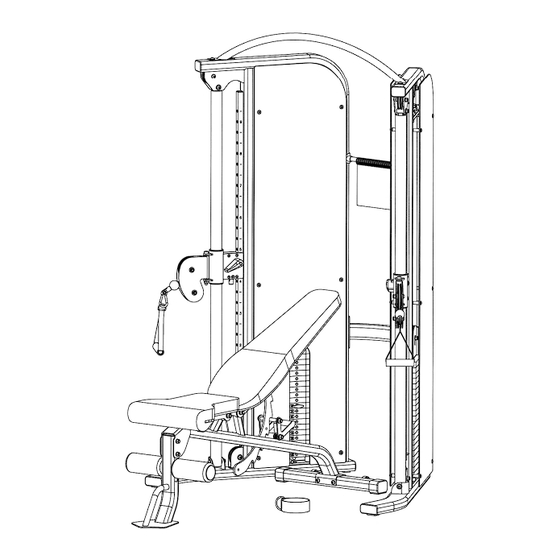
- Page 1 NOTE: Please read all instructions carefully before using this product IRON GRIP STRENGTH Table of Contents POWER SYSTEM Safety Notice Hardware Identifier IGS-6500 Assembly Instruction Parts List Warranty Ordering Parts Model IGS-6500 Retain This Manual for Reference 11-26-07 OWNER'S MANUAL ®...
-
Page 2: Table Of Contents
MULTI-PURPOSE BENCH EXPLODED DIAGRAM……………………………. 20 MULTI-PURPOSE BENCH PARTS LIST………………………………………… 21 WARRANTY....................… 22 ORDERING PARTS..................22 BEFORE YOU BEGIN Thank you for selecting the IRON GRIP STRENGTH IGS-6500 POWER ® SYSTEM by IMPEX INC. For your safety and benefit, read this manual carefully before using the machine. -
Page 3: Important Safety Notices
IMPORTANT SAFETY NOTICE PRECAUTIONS This exercise machine is built for optimum safety. However, certain precautions apply whenever you operate a piece of exercise equipment. Be sure to read the entire manual before you assemble or operate your machine. In particular, note the following safety precautions: 1. -
Page 4: Warning Label Placement
WARNING LABEL PLACEMENT The warning labels have been placed on the unit in location shown. If the labels are missing or illegible, please call customer service at 1-800-888-8899 for replacements. Apply the labels in location shown. -
Page 5: Functional Trainer Hardware Pack
FUNCTIONAL TRAINER HARDWARE PACK... -
Page 6: Functional Trainer Assembly Instructions
FUNCTIONAL TRAINER ASSEMBLY INSTRUCTION Tools Required Assembling the Machine: Crossing Wrench and Allen Wrenches. NOTE: Two or more people assembling this machine is a must. Do NOT attempt to assemble this machine alone. STEP 1 (See Diagram 1) A.) Place the Cross Brace (#4) between the Right & Left Stations (#1 & #2) in the mid-span. B.) Attach one end of the Cross Brace to the Right Station. - Page 7 STEP 2 (See Diagram 2) A.) Lift up the Selector Stem (#19) on the Right Station (#1) and hold it still to release the tension on the cables. Remove the two M10 x ¾” Allen Bolts (#67), Ø ¾” Spring Washers (#74), and Ø...
- Page 9 STEP 3 (See Diagram 3) A.) Peel off the cover paper on the surface of the Right Outer Cover (#32) and Right Inner Cover (#34). B.) Attach the Right Outer Cover to the Right Station from the outside. Secure it with six M6 x 1 ¾”...
- Page 10 STEP 4 (See Diagram 4) A.) Attach one Hanger Bracket (#15) to the Right Station (#1). Secure it with two M6 x 5/8” Allen Bolts (#44) and Ø ½” Washers (#59). Do not tighten the Bolts yet. B.) Slide the Flip Exercise Chart onto the Hanger (#16). C.) Attach the Hanger (#16) to the Brackets (#15).
- Page 11 STEP 5 (See Diagram 6 & Cable Loop Diagram) A.) Attach the Height Adjustment Handle (#36) to the Right Lock Switch (#10) on the Pulley Carriage (#8). Secure it with one M5 x 3/8” Allen Bolt (#71). Repeat the same procedure to install the other side.
-
Page 12: Weight Resistance Chart
WEIGHT RESISTANCE CHART Plate Label 17.5 20.0 22.5 25.0 27.5 30.0 32.5 35.0 37.5 *Numbers are approximate, actual value may vary. -
Page 14: Functional Trainer Parts List
PARTS LIST KEY NO. DESCRIPTION Q’ty Right Station Ø ¾” Pulley Bushing Left Station Rubber Spacer Chin-up Bar 1” Square End Cap Cross Brace Hook Chrome Slide Tube ST4.2 x 5/8” Philips Screw Right Carriage Support Frame Ø 1” Clip Left Carriage Support Frame Ø... -
Page 15: Multi-Purpose Bench Hardware Pack
MULTI-PURPOSE BENCH HARDWARE PACK... -
Page 16: Multi-Purpose Bench Assembly Instructions
MULTI-PURPOSE BENCH ASSEMBLY INSTRUCTION Tools Required Assembling the Machine: One Adjustable Wrench and Allen Wrenches. NOTE: It is strongly recommended this machine be assembled by two or more people to avoid possible injury. STEP 1 (See Diagram 1) A.) Attach the Main Seat Support (#9) onto the Front Post (#8). B.) Secure it with two M10 x 3 ¾”... - Page 17 STEP 2 (See Diagram 2) A.) Attach the Main Seat Support (#9) onto the Rear Stabilizer (#13). B.) Secure it with two M10 x 3 ¾” Carriage Bolts (#29), four Ø ¾” Washers (#3), and two M10 Aircraft Nuts (#28). C.) Securely tighten all Nuts and Bolts installed.
- Page 18 STEP 3 (See Diagram 3) A.) Insert the Foam Tube (#15) halfway through the hole on the Front Post (#8). B.) Push two Foam Rolls (#27) onto the Tube from both ends. Plug two Foam Roll End Caps (#1) into the ends. DIAGRAM 3...
- Page 19 STEP 4 (See Diagram 4) A.) Place the Seat Pad (#19) onto the Left & Right Seat Brackets (#16 & #17). B.) Secure it with four M8 x ¾” Allen Bolts (#36) and Ø 5/8” Washers (#6). DIAGRAM 4...
- Page 20 STEP 5 (See Diagram 5) A.) Attach the Backrest Board (#18) to the Backrest Support (#10). B.) Secure it with three M8 x 2 5/8” Allen Bolts (#37) and Ø 5/8” Washers (#6). C.) When adjusting the Backrest Board to an incline position, simply pull up the Board. When adjusting the Board to decline or flat positions, press or step down on the Backrest Adjustment Lever (#14) to disengage the Lever to allow the Board to go down.
-
Page 21: Multi-Purpose Bench Exploded Diagram
MULTI-PURPOSE BENCH EXPLODED DIAGRAM... -
Page 22: Multi-Purpose Bench Parts List
MULTI-PURPOSE BENCH PARTS LIST KEY NO. DESCRIPTION Q’ty Foam Roll End Cap Wheel Ø ¾” Washer Ø 1” Washer Ø 1 3/8” Washer Ø 5/8” Washer Ø 1” Bushing Front Post Main Seat Support Backrest Support Backrest Incline Support Seat Incline Support Rear Stabilizer Backrest Adjustment Lever Foam Tube... -
Page 23: Warranty
® IMPEX INC. LIMITED WARRANTY ® IMPEX Inc. ("IMPEX ") warrants this product to be free from defects in workmanship and material, under normal use and service conditions, for a period of two years on the Frame from the date of purchase. This warranty extends only to the original purchaser.
Need help?
Do you have a question about the IGS-6500 and is the answer not in the manual?
Questions and answers