Advertisement
NOTE:
Please read all instructions
carefully before using this
product
Table of Contents
Safety Notice
Hardware Pack
EVERLAST
Assembly Instruction
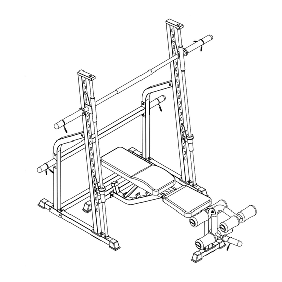
SMITH BENCH
Parts List
Warranty
EVE-890
Ordering Parts
Model
EVE-890
Retain This
Manual for
Reference
08-16-05
OWNER'S
MANUAL
Made under license from trademark owner Everlast Worldwide
Inc., New York.
IMPEX INC.
14777 DON JULIAN RD., CITY OF INDUSTRY, CA 91746
Tel: (800) 999-8899 Fax: (626) 961-9966
www.impex-fitness.com
info@impex-fitness.com
Advertisement
Table of Contents

Subscribe to Our Youtube Channel
Related Manuals for Everlast EVE-890


Summary of Contents for Everlast EVE-890
- Page 1 Table of Contents Safety Notice Hardware Pack EVERLAST Assembly Instruction SMITH BENCH Parts List Warranty EVE-890 Ordering Parts Model EVE-890 Retain This Manual for Reference 08-16-05 OWNER'S MANUAL Made under license from trademark owner Everlast Worldwide Inc., New York.
-
Page 2: Table Of Contents
WARRANTY...… ORDERING PARTS... BEFORE YOU BEGIN Thank you for selecting the EVERLAST Smith Machine EVE-890 by IMPEX INC. For your safety and benefit, read this manual carefully before using the machine. As a manufacturer, we are committed to provide you complete customer satisfaction. -
Page 3: Important Safety Notice
PHYSICIAN. THIS IS ESPECIALLY IMPORTANT FOR INDIVIDUALS OVER THE AGE OF 35 OR PERSONS WITH PRE-EXISTING HEALTH PROBLEMS. INSTRUCTIONS BEFORE USING ANY FITNESS EQUIPMENT. ASSUMES NO RESPONSIBILITY FOR PERSONAL INJURY OR PROPERTY DAMAGE SUSTAINED BY OR THROUGH THE USE OF THIS PRODUCT. SAVE THESE INSTRUCTIONS. READ ALL IMPEX INC. -
Page 4: Warning Label Replacement
WARNING LABEL REPLACEMENT The warning label shown here has been placed on the Cross Brace. If the label is missing or illegible, please call customer service at 1-800-888-8899 for replacement. Apply the label in the location shown. -
Page 5: Hardware Pack
HARDWARE PACK... -
Page 6: Assembly Instructions
ASSEMBLY INSTRUCTION Tools Required Assembling the Machine: Two Adjustable Wrenches and Allen Wrenches. NOTE: It is strongly recommended two or more people assembling this machine to avoid possible injury. STEP 1 (See Diagram 1) Note: Do not tighten the nuts and bolts until instructed to do so. Plug four 2”... - Page 7 STEP 2 (See Diagram 2) A.) Slide both a Rubber Bumper (#26) and Safety Stop (#6) onto a Guide Rod (#5). B.) Slide a Sliding Bar Catch (#8) onto the Guide Rod. C.) Insert the bottom of the Guide Rod into the ring cap on the left Stabilizer. Insert the top of Guide Rod into the ring cap on top of the left Upright Beam.
- Page 8 STEP 3 (See Diagram 3) A.) NOTE: Help of another person is strongly recommended for this step. Place the Lifting Sleeve (#10) in between the two Sliding Bar Catches (#8). Align the holes and insert the Weight Bar (#9) into the Bar Catch from one end and through the Lifting Sleeve to the other Bar Catch on the opposite end.
- Page 9 STEP 4 (See Diagram 4) A.) Plug four Stabilizer End Caps (#24) onto each end of the Front and Rear Stabilizers (#35 & #36). B.) Attach the Main Seat Support (#30) to the Rear & Front Stabilizers (#35 & #36). Secure each end with one 4 ¾”...
- Page 10 STEP 5 (See Diagram 5) A.) Attach the side-holes on the Backrest Supports (#33) to the long pivot on the Main Seat Support (#30). Insert one M10 x 7 ¼” Allen Bolt (#47) through the holes and secure it with two Ø ¾” Washers (#14), and one M10 Aircraft Nut (#17). B.) Place the Backrest Incline Support (#34) in between the two Backrest Supports (#33).
- Page 11 STEP 6 (See Diagram 6) A.) Place the Backrest Board (#32) onto the Backrest Supports. Secure it with four M6 x 2 1/8” Hex Bolts (#50) and ؽ” Washers (#49). B.) Place the Seat (#34) onto the Seat Incline Support. Secure it with four M6 x 5/8” Hex Bolts (#53) and Ø...
-
Page 13: Parts List
PARTS LIST KEY NO. DESCRIPTION Stabilizer Rear Support Upright Beam Cross Brace Guide Rod Safety Stop Safety Hook Sliding Bar Catch Weight Bar Lifting Sleeve Weight Storage Post 4 ¾” x 2” Bracket 6 ¼” x 2” Bracket ¾” Washer M10 x 5/8”... -
Page 14: Warranty
IMPEX. IMPEX is not responsible or liable for indirect, special or consequential damages arising out of or in connection with the use or performance of the product or other damages with respect to any economic loss, loss of property, loss of revenues or profits, loss of enjoyments or use, costs of removal, installation or other consequential damages or whatsoever natures.
Need help?
Do you have a question about the EVE-890 and is the answer not in the manual?
Questions and answers