Advertisement
NOTE:
Please read all
instructions carefully
before using this product
Table of Contents
Safety Notice
Hardware Pack
Assembly Instruction
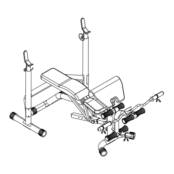
Exploded Diagram
Parts List
Warranty
Ordering Parts
Model
EVE-840
Retain This
Manual for
Reference
07/06/05
OWNER'S
MANUAL
EVERLAST
EVE-840 WEIGHT BENCH
Made under license from trademark owner Everlast
Worldwide Inc., New York.
14777 Don Julian Rd., City of Industry, CA 91746
Tel: (800) 999-8899 Fax (626) 961-9966
www.impex-fitness.com
info@impex-fitness.com
IMPEX INC.
Advertisement
Table of Contents

Related Manuals for Everlast EVE-840


Summary of Contents for Everlast EVE-840
- Page 1 Retain This Manual for Reference 07/06/05 OWNER'S MANUAL EVERLAST EVE-840 WEIGHT BENCH Made under license from trademark owner Everlast Worldwide Inc., New York. IMPEX INC. 14777 Don Julian Rd., City of Industry, CA 91746 Tel: (800) 999-8899 Fax (626) 961-9966 www.impex-fitness.com...
-
Page 2: Table Of Contents
WARRANTY... ORDERING PARTS... BEFORE YOU BEGIN Thank you for selecting the EVERLAST EVE-840 BENCH by IMPEX INC. For your safety and benefit, read this manual carefully before using the machine. As a manufacturer, we are committed to provide you complete customer satisfaction. -
Page 3: Important Safety Notice
OVER THE AGE OF 35 OR PERSONS WITH PRE-EXISTING HEALTH PROBLEMS. READ ALL INSTRUCTIONS BEFORE USING ANY FITNESS EQUIPMENT. IMPEX INC. ASSUMES NO RESPONSIBILITY FOR PERSONAL INJURY OR PROPERTY DAMAGE SUSTAINED BY OR THROUGH THE USE OF THIS PRODUCT. SAVE THESE INSTRUCTIONS. -
Page 4: Warning Label Replacement
WARNING LABEL REPLACEMENT The Warning Label shown here has been placed on the Front Stabilizer. If the label is missing or illegible, please call customer service at 1-800-999-8899 for replacement. Apply the label in location shown. -
Page 5: Hardware Pack
HARDWARE PACK... - Page 6 HARDWARE PACK...
-
Page 7: Assembly Instructions
ASSEMBLY INSTRUCTION Tools Required Assembling the Machine: Two Adjustable Wrenches and Allen Wrenches. NOTE: It is strongly recommended two or more people assembling this machine to avoid possible injury. STEP 1 (See Diagram 1) A.) Connect the Right Upright Beam (#3) to a Rear Stabilizer (#14). Make sure this Stabilizer does not have Roller End Cap (#59) on its ends. - Page 8 STEP 2 (See Diagram 2) A.) Connect the Main Seat Support (#1) to a Rear Stabilizer (#14). Make sure this Stabilizer has two Roller End Caps (#59). Secure them with one Bent Bracket (#17), two M10 x 3 ¾” Carriage Bolts (#47), two B.) Connect the Main Seat Support (#1) to the Front Stabilizer (#5).
- Page 9 STEP 3 (See Diagram 3) A.) Attach two Ø ¾” Bushings (#54) to the pivot on the Main Seat Support (#1). B.) Attach two Backrest Supports (#7) to the Pivot and align the holes. Secure it with one M10 x 6 ¼” Allen Bolt (#39), two C.) Attach two Ø...
- Page 10 STEP 4 (See Diagram 4) A.) Attach two Ø ¾” Bushings (#54) to the pivot on the Main Seat Support (#1). Attach the Seat Incline Support Bracket (#8) to the Bushings and align the holes. Secure it with one M10 x 4 ½” Allen Bolt (#40), two Ø ¾” Washers (#48), and one M10 Aircraft Nut (#50). B.) Attach two Ø...
- Page 11 STEP 5 (See Diagram 5) A.) Attach four Ø ¾” Bushings (#54) to the two Seat Support Frames (#6). Attach another four 3/4” Bushings (#54) to the two Backrest Supports (#7). B.) Attach a Backrest Support (#7) to a Seat Support Frame (#6). Please note that the Backrest Support should be on the inside of the Seat Support Frame.
- Page 12 STEP 6 (See Diagram 6) A.) Place the Seat (#22) onto the Seat Support Frame (#6). Secure it with four M8 x 2” Allen Bolts (#44) and Ø5/8” Washers (#49). B.) Place the Backrest Board (#23) onto the Backrest Supports (#7). Secure it with four M8 x 2”...
- Page 13 STEP 7 (See Diagram 7) A.) Attach the Leg Developer (#4) to the bracket on the top of Main Seat Support (#1). Secure it with one Axle (#16), two M10x ¾” Allen Bolts (#43), and ؾ” Washers (#48). B.) Insert one Foam Roll Tube (#15) halfway through the hole on the Main Seat Support. Insert two Foam Roll Tubes halfway through the holes on the Leg Developer.
-
Page 15: Parts List
PARTS LIST KEY NO. DESCRIPTION Main Seat Support Left Upright Beam Right Upright Beam Leg Developer Front Stabilizer Seat Support Frame Backrest Support Seat Incline Support Bracket Arm Curl Stand Sliding Block Incline Adjustment Bar Crutch Cross Brace Rear Stabilizer Foam Roll Tube Axle Bent Bracket... -
Page 16: Warranty
IMPEX. IMPEX is not responsible or liable for indirect, special or consequential damages arising out of or in connection with the use or performance of the product or other damages with respect to any economic loss, loss of property, loss of revenues or profits, loss of enjoyments or use, costs of removal, installation or other consequential damages or whatsoever natures.
Need help?
Do you have a question about the EVE-840 and is the answer not in the manual?
Questions and answers