Table of Contents
Advertisement
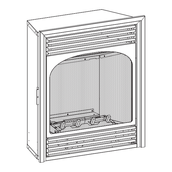
The Vail Vent-Free Gas Fireplaces
This appliance may be installed in an aftermarket,
permanently located, manufactured (mobile) home,
where not prohibited by local codes.
This appliance is only for use with the type of gas in-
dicated on the rating plate. This appliance is not con-
vertible for use with other gases.
WARNING: If the information in these instructions
are not followed exactly, a fire or explosion may
result causing property damage, personal injury or
loss of life.
— Do not store or use gasoline or other flammable
vapors and liquids in the vicinity of this or any
other appliance.
— WHAT TO DO IF YOU SMELL GAS
•
Do not try to light any appliance.
•
Do not touch any electrical switch; do not use
any phone in your building.
•
Immediately call your gas supplier from a
neighbor's phone. Follow the gas supplier's
instructions.
•
If you cannot reach your gas supplier, call the
fire department.
— Installation and service must be performed by a
qualified installer, service agency or the gas sup-
plier.
INSTALLATION INSTRUCTIONS
OWNER'S MANUAL
AND
UNVENTED GAS FIREPLACE
HYDRAULIC THERMOSTAT
MODELS:
VFP24FP2(0,1,2,3)L(N,P)-1
MILLIVOLT MODELS:
VFP24FP3(0,1,2,3)L(N,P)-1
VFP24FP3(0,1,2,3)L10(N,P)-1 (10,000 BTU UNIT)
INTERMITTENT PILOT MODELS:
VFP24FP7(0,1,2,3)L(N,P)-1
VFP24FP7(0,1,2,3)L10(N,P)-1 (10,000 BTU UNIT)
Installer:
Leave this manual with the appliance.
Consumer: Retain this manual for future reference.
This is an unvented gas-fired heater. It uses air (oxy-
gen) from the room in which it is installed. Provisions
for adequate combustion and ventilation air must be
provided. Refer to page 6.
WARNING: If not installed, operated and maintained
in accordance with the manufacturer's instructions,
this product could expose you to substances in fuel
or from fuel combustion which can cause death or
serious illness.
WATER VAPOR: A BY-PRODUCT OF UNVENTED
ROOM HEATERS
Water vapor is a by-product of gas combustion. An
unvented room heater produces approximately one
ounce (30ml) of water for every 1,000 BTU's (.3KW's)
of gas input per hour. Refer to page 6.
Page 1
Advertisement
Table of Contents
Troubleshooting

Related Manuals for White Mountain VFP24FP2 Series


Summary of Contents for White Mountain VFP24FP2 Series
-
Page 1: Installation Instructions
INSTALLATION INSTRUCTIONS OWNER'S MANUAL The Vail Vent-Free Gas Fireplaces UNVENTED GAS FIREPLACE HYDRAULIC THERMOSTAT MODELS: VFP24FP2(0,1,2,3)L(N,P)-1 MILLIVOLT MODELS: VFP24FP3(0,1,2,3)L(N,P)-1 VFP24FP3(0,1,2,3)L10(N,P)-1 (10,000 BTU UNIT) INTERMITTENT PILOT MODELS: VFP24FP7(0,1,2,3)L(N,P)-1 VFP24FP7(0,1,2,3)L10(N,P)-1 (10,000 BTU UNIT) This appliance may be installed in an aftermarket, permanently located, manufactured (mobile) home, where not prohibited by local codes. -
Page 2: Table Of Contents
TABLE OF CONTENTS SECTION PAGE IMPORTANT SAFETY INFORMATION ..............3 SAFETY INFORMATION FOR USERS OF LP-GAS ..........4 INTRODUCTION ......................5 SPECIFICATIONS ....................6 WATER VAPOR: A BY-PRODUCT OF UNVENTED ROOM HEATERS ....6 PROVISIONS FOR ADEQUATE COMBUSTION & VENTILATION AIR ....6-7 GAS SUPPLY ......................8 CLEARANCES ......................9 COMBUSTIBLE MATERIAL ..................9 INSTALLATION OF FIREPLACE INTO MANTEL ..........10... -
Page 3: Important Safety Information
IMPORTANT SAFETY INFORMATION THIS IS A HEATING APPLIANCE DANGER: Indicates a hazardous situation which, if not avoided, will • WARNING! This fireplace needs fresh air for ventilation to result in death or serious injury. run properly. This fireplace has an ODS (oxygen depletion sensor) which will shut down the heater if adequate fresh air is WARNING: Indicates a hazardous situation which, if not avoided, not available. -
Page 4: Safety Information For Users Of Lp-Gas
SAFETY INFORMATION FOR USERS OF LP-GAS Propane (LP-Gas) is a flammable gas which can cause fires SOME POINTS TO REMEMBER and explosions. In its natural state, propane is odorless and • Learn to recognize the odor of LP-gas. Your local LP-Gas colorless. -
Page 5: Introduction
INTRODUCTION Instructions to Installer Any alteration of the original design, installed other than as 1. Installer must leave instruction manual with owner after shown in these instructions or use with a type of gas not installation. shown on the rating plate is the responsibility of the person 2. -
Page 6: Specifications
SPECIFICATIONS Accessories VFP24FP3*L Model VFP24FP2*L VFP24FP3*L10 VFP24FP7*L FBB6 Automatic Blower Input Max. 20,000 20,000 10,000 VPP1A-22 Aged Brick Liner Input Min. 14,000 10,000 10,000 VFF24BR-1 Brass Trim Kit Fireplace Dimensions VFF24SS-1 Stainless Steel Trim Kit Height 26 3/8" 26 3/8" 26 3/8"... - Page 7 3. Add the BTU/Hr of all fuel burning appliances in the space. Vent-free heater BTU/Hr Gas water heater BTU/Hr Gas furnace BTU/Hr Vented gas heater BTU/Hr Gas fireplace logs BTU/Hr Other gas appliances* + BTU/Hr Total BTU/Hr Example: Vented gas heater 20,000 BTU/Hr Vent-free heater...
-
Page 8: Gas Supply
GAS SUPPLY Check all local codes for requirements, especially for the size and Pressure Testing of the Gas Supply System type of gas supply line required. To check the inlet pressure to the gas valve, a 1/8" (3mm) N.P.T. plugged tapping, accessible for test gauge connection, must be placed immediately upstream of the gas supply connection Recommended Gas Pipe Diameter to the appliance. -
Page 9: Clearances
CLEARANCES Minimum Wall and Ceiling Clearances Mantel Clearances for Built-in Installation 30” (762mm) Figure 4 This fireplace can be installed with zero clearance to combustible material. When facing the front of the appliance the minimum clearances to combustible construction (material) are the following: Clearances from the right side or left side of the fireplace opening to any combustible wall or material should not be less than 4 inches. -
Page 10: Installation Of Fireplace Into Mantel
INSTALLATION OF FIREPLACE INTO MANTEL Installing Fireplace in Mantel Position base approximately 5" from wall surface. Attach nailing flange to fireplace top with two 10 x 1/2" screws. Place fireplace on top of base. Gas line connections must be made at this time. When facing the fireplace the gas supply will enter on right-hand side. -
Page 11: Built-In Fireplace Installation
BUILT-IN FIREPLACE INSTALLATION Built-In Fireplace Installation Rough Opening for Installing in Corner Built-in installation of this fireplace involves installing fireplace into a framed-in enclosure. This makes the front of fireplace flush with wall. If installing a mantel above the fireplace, you must follow the clearances shown in Figure 5, page 9. -
Page 12: Placement Of Glowing Embers (Rock Wool)
PLACEMENT OF GLOWING EMBERS (ROCK WOOL) Provided with the log set is a small bag of glowing embers (rock Replacement of loose material (glowing embers) must be purchased wool) to be placed between logs on the flat metal surface of the from Empire Comfort Systems, Inc. -
Page 13: Millivolt Control Lighting Instructions
MILLIVOLT CONTROL LIGHTING INSTRUCTIONS FOR YOUR SAFETY READ BEFORE LIGHTING WARNING: If you do not follow these instructions exactly, a fire or explosion may result causing property damage, personal injury or loss of life. A. This appliance has a pilot which must be lighted by C. -
Page 14: 10,000 Btu Millivolt Control Valve Lighting Instructions
10,000 BTU MILLIVOLT CONTROL VALVE LIGHTING INSTRUCTIONS FOR YOUR SAFETY READ BEFORE LIGHTING WARNING: If you do not follow these instructions exactly, a fire or explosion may result causing property damage, personal injury or loss of life. A. This appliance has a pilot which must be lighted by hand. C. -
Page 15: Hydraulic Thermostat Models Lighting Instructions
HYDRAULIC THERMOSTAT MODELS LIGHTING INSTRUCTIONS FOR YOUR SAFETY READ BEFORE LIGHTING WARNING: If you do not follow these instructions exactly, a fire or explosion may result causing property damage, personal injury or loss of life. A. This appliance has a pilot which must be lighted by C. -
Page 16: Intermittent Pilot Lighting Instructions
INTERMITTENT PILOT LIGHTING INSTRUCTIONS FOR YOUR SAFETY READ BEFORE LIGHTING WARNING: If you do not follow these instructions exactly, a fire or explosion may result causing property damage, personal injury or loss of life. A. This appliance has a pilot which must be lighted by hand. When C. -
Page 17: Log Placement
LOG PLACEMENT Before you begin: Do not, handle these logs with your bare hands! Always wear gloves to prevent skin irritation. After handling logs, wash your hands gently with soap and water. All Logs The positioning of the logs is critical to the safe and clean operation of this heater. -
Page 18: Pilot Flame Characteristics
PILOT FLAME CHARACTERISTICS Figures 13, 14 and 15 show a correct pilot flame pattern. The correct flame meet. Figures 16, 17 and 18 show an incorrect pilot flame flame will be blue and will extend beyond the thermocouple. The pattern. The incorrect pilot flame is not touching the thermocouple. flame will surround the thermocouple just below the tip. - Page 19 PILOT FLAME CHARACTERISTICS Incorrect Pilot Flame Pattern PILOT THERMOPILE THERMOCOUPLE THERMOCOUPLE (NATURAL) (LPG) Millivolt Pilot, Figure 16 PILOT THERMOCOUPLE THERMOCOUPLE (NATURAL) (LPG) Hydraulic Thermostat Pilot, Figure 17 IGNITOR SENSOR PILOT Intermittant Pilot, Figure 18 If pilot flame pattern is incorrect as shown in Figures 16 and 17 •...
-
Page 20: Main Burner And Thermostat Operation
Millivolt Pilot Figure 19 Hydraulic Thermostat Pilot Figure 20 MAIN BURNER AND THERMOSTAT OPERATION The VFP24FP2 Series gas control maximum and minimum Cleaning and Maintenance / Main Burner inputs are listed below. WARNING OFF is the OFF position. Turn off heater and let cool before cleaning. -
Page 21: Millivolt Wiring
MILLIVOLT WIRING Label all wires prior to disconnection when servicing controls. Wiring Remote Receiver errors can cause improper and dangerous operation. Verify proper Use the following steps to place the remote receiver adjacent to operation after servicing. the gas valve. Attention: The remote receiver bracket is not used in this Millivolt thermopile is self powered, gas valve does not require 110 installation. -
Page 22: Millivolt Troubleshooting
MILLIVOLT TROUBLESHOOTING SYMPTOMS, POSSIBLE CAUSES AND CORRECTIONS Turn appliance OFF and allow to cool before servicing. Only a qualified service person should service and repair the heater. When ignitor button is pressed, there is no spark at ODS/ pilot lights, keep control knob pressed in 30 seconds. pilot. -
Page 23: Intermittant Control System Operating Instructions
INTERMITTANT CONTROL SYSTEM OPERATING INSTRUCTIONS 5.25 VDC ELECTRONIC CONTROL VALVE Follow the SAFETY and LIGHTING INSTRUCTIONS for In- termittent Pilot controls found in this manual, and on labels The electronic control valve system includes the ability to switch found in the control compartment located in the lower cavity the pilot from a standing pilot mode to an intermittent pilot mode. -
Page 24: Intermittant Control System Wiring Diagram
INTERMITTANT CONTROL SYSTEM WIRING DIAGRAM If any of the original wire as supplied with this unit must be replaced, it must be replaced with equivalent gauge and tem- perature rated wire. This appliance is only for use with the type of gas indicated on the rating plate and may be installed in an aftermarket, permanently located, manufactured (mobile) home where not prohibited by local codes. -
Page 25: Intermittent Control System Troubleshooting
INTERMITTENT CONTROL SYSTEM TROUBLESHOOTING Brief Description of the Components The gas valve is fitted with a manual HI/LO knob to allow for man- ual modulation of the gas outlet pressure to the appliance burner. The controls are designed to be used with either LPG or Natural Gas and can be converted by use of an OEM supplied conversion kit. - Page 26 INTERMITTENT CONTROL SYSTEM TROUBLESHOOTING If the DFC giving signal lock out: Verify the electrical connections’ integrity and The board should be unlocked to make sure they are in accordance with the relevant reinitiate a pilot flame ignition (for Is the DFC board in system wiring diagram.
-
Page 27: Intermittent Control System Troubleshooting
INTERMITTENT CONTROL SYSTEM TROUBLESHOOTING Replace DFC board. Main burner lights when the pilot only Replace the gas valve. should light. Verify the pilot flame fully engulfs the tip of the sense electrode. If not replace the pilot assembly. Replace the pilot assembly. Carefully clean the electrical connections of the sense cable, and the DFC board sense cable connection. -
Page 28: Parts List
PARTS LIST ATTENTION: When ordering parts, it is very important that part number and description of part coincide. INDEX PART INDEX PART DESCRIPTION DESCRIPTION COMMON VFP24FP30L and VFP24FP30L10 25897 TRIM - TOP R3623 PILOT ASSEMBLY - LPG 25895 TRIM - LEFT R3624 PILOT ASSEMBLY - NAT 25896... -
Page 29: Parts List
PARTS LIST ATTENTION: When ordering parts, it is very important that part number and description of part coincide. INDEX PART DESCRIPTION INDEX PART DESCRIPTION VFP24FP70L VFP24FP70L10 R11328 PILOT ASSEMBLY, NAT R11328 PILOT ASSEMBLY, NAT R11327 PILOT ASSEMBLY, LP R11327 PILOT ASSEMBLY, LP R5676 AIR SHUTTER - NAT R5676... -
Page 30: Parts View
PARTS VIEW VFP24FP7 Series VFP24FP2 Series VFP24FP3 Series 34 33 Page 30 30411-9-0714... -
Page 31: Optional Brick Liner Installation Instructions
OPTIONAL BRICK LINER INSTALLATION INSTRUCTIONS VPP1A-22 INSTALLING OPTIONAL BRICK LINER Remove screen assembly from fireplace. Remove logs from burner assembly. Insert rear brick liner and two side brick liners onto bottom of the inner casing. Align grout lines on rear brick liner with grout lines on side brick liners. -
Page 32: Optional Blower Installation Instructions
OPTIONAL BLOWER INSTALLATION INSTRUCTIONS FBB6 Blower Insert blower assembly in left side of outer casing. Motor with wiring will be to the inside of the outer casing, blower chute will INSTALLING OPTIONAL BLOWER be facing upward. See Figure 28. Remove bottom louver. Remove upper louver. - Page 33 OPTIONAL BLOWER INSTALLATION INSTRUCTIONS 12. Route wires from fan control behind inner casing to bottom of 26. Replace burner assembly. outer casing. 27. Attach burner assembly to blower shield with one 13. Snap Heyco bushing into blower shield side. 10 x 1/2" screw. See Figure 32. 14.
- Page 34 OPTIONAL BLOWER INSTALLATION INSTRUCTIONS (cont.) Wiring CAUTION The appliance, when installed, must be electrically grounded in accordance with local codes or, in the absence of local codes, Label all wires prior to disconnection when servicing controls. with the National Electrical Code ANSI/NFPA No. 70, if an external Wiring errors can cause improper and dangerous operation.
-
Page 35: Optional Blower Installation Instructions
OPTIONAL BLOWER INSTALLATION INSTRUCTIONS (cont.) FBB6 PARTS LIST Index Part Description Number 11508 FAN CONTROL BRACKET R2503 FAN CONTROL 11301 BLOWER DIVERTER R2099 CORD SET R1410 STRAIN RELIEF BUSHING 25794 BLOWER BASE ASSEMBLY R2804A BLOWER ASSEMBLY R5804 WIRE HARNESS R1404 SNAP BUSHING 11507 BLOWER SHIELD - SIDE... -
Page 36: Parts List And Parts View For Optional Trim Kits
PARTS LIST AND PARTS VIEW FOR OPTIONAL TRIM KITS Attention: When ordering parts, it is very important that the part number and description coincide. Index Number Part Number Description VFF24BR Brass Trim Kit 25974 Trim Top 25972 Trim Left 25973 Trim Right VFF24SS Stainless Steel Trim Kit 25982... -
Page 37: Master Parts Distributor List
MASTER PARTS DISTRIBUTOR LIST To Order Parts Under Warranty, please contact your local Empire dealer. See the dealer locator at www.empirecomfort. com. To provide warranty service, your dealer will need your name and address, purchase date and serial number, and the nature of the problem with the unit. -
Page 38: Appliance Service History
APPLIANCE SERVICE HISTORY Date Dealer Name Service Technician Name Service Performed/Notes Page 38 30411-9-0714... -
Page 39: Appliance Service History
APPLIANCE SERVICE HISTORY Date Dealer Name Service Technician Name Service Performed/Notes 30411-9-0714 Page 39... -
Page 40: Warranty
WARRANTY Empire Comfort Systems Inc. warranties this hearth product to be free from defects at the time of purchase and for the periods speci- fied below. Hearth products must be installed by a qualified technician and must be maintained and operated safely, in accordance with the instructions in the owner’s manual.
Need help?
Do you have a question about the VFP24FP2 Series and is the answer not in the manual?
Questions and answers