
Related Manuals for AMX Power Current Sensors PCS


Summary of Contents for AMX Power Current Sensors PCS
- Page 1 instruction manual PCS and PCS2 Power Current Sensors C o n t r o l S y s t e m A c c e s s o r i e s...
- Page 2 This warranty extends only to products purchased directly from AMX Corporation or an Authorized AMX Dealer. AMX Corporation is not liable for any damages caused by its products or for the failure of its products to perform. This includes any lost profits, lost savings, incidental damages, or consequential damages. AMX Corporation is not liable for any claim made by a third party or by an AMX Dealer for a third party.
-
Page 3: Table Of Contents
Table of Contents Product Information ...1 Specifications ... 1 Installation ...3 PCS and PCS2 Installation ... 3 Rack mounting the PCS2 ... 3 Wiring Guidelines ... 3 Preparing captive wires... 4 PCS to AXC-INP8 ... 4 PCS2 to AXC-INP8 ... 5 PCS to Axcent, Axcent2, or Axcent3... - Page 4 Table of Contents PCS and PCS2 Power Current Sensors...
-
Page 5: Product Information
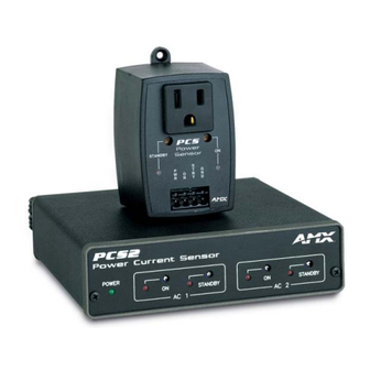
The Power Current Sensors (PCS) and Dual Power Current Sensors (PCS2) provide power current status for AMX equipment. Examples of such equipment are video projectors, monitors, audio receivers, and VCRs. The PCS and PCS2 detect the AC current drawn by the equipment plugged into its AC receptacle. - Page 6 Product Information PCS and PCS2 Power Current Sensors...
-
Page 7: Installation
Installation The PCS requires +12 VDC (+11 VDC to +17 VDC @ 20 mA minimum) for operation; the PCS2 is simply plugged into a 120 VAC three-hole wall outlet to obtain power. PCS and PCS2 Installation 1. Provide +12 VDC power from the Central Controller or external power supply, and connect it to the port on the PCS. -
Page 8: Preparing Captive Wires
Installation Do not connect power to the PCS/PCS2 until the wiring is complete. Preparing captive wires You will need a wire stripper and flat-blade screwdriver to prepare and connect the captive wires. Never pre-tin wires for compression-type connections. 1. Strip 0.25 inch (6.35 mm) of insulation off all wires. 2. -
Page 9: Pcs2 To Axc-Inp8
PCS2 to AXC-INP8 Connect the PCS2 output ports to the AXC-INP8 input ports, as illustrated in FIG. 2. Follow the illustration for Input 1 through Input 8. Set the jumpers of the associated inputs on the AXC-INP8 to Switch mode. All Switch mode inputs and the Card-Frame share common GND. INP1 AXC-INP8 INP2... -
Page 10: Pcs To Television Controllers
Installation PCS to Television Controllers FIG. 5 illustrates the connections required for the PCS to television controllers. I/O 1 Television controllers I/O 2 I/O 3 I/O 4 FIG. 5 PCS to television controllers PCS2 to Television Controllers FIG. 6 illustrates the connections between the PCS2 to television controllers. I/O 1 Television controllers... -
Page 11: Calibration
Calibration The PCS and PCS2 work by setting a threshold. The STANDBY threshold is set be-tween the current draw of the OFF state and that of the STANDBY state. The ON threshold is then set between the current draw of the STANDBY state and the ON state. The PCS2 contains two major circuits, each independent of each other. - Page 12 Calibration FIG. 7 Standby and On level relationship If the unit has both STANDBY and ON states, follow these steps: If the unit only has an ON state, or if the PCS is sensing the ON state, perform step 1. If you are using only the STANDBY mode, focus on steps 3 and 4.
-
Page 13: Pcs2 Calibration
PCS2 Calibration When extreme accuracy is required for calibration, allow the PCS2 to warm up for a minimum of 15 minutes before calibration. The following procedures are used for both circuit 1 and circuit 2. Calibrate each circuit independently. If the device only has an ON state, either STANDBY or ON can be used in the following steps. 1. - Page 14 Calibration PCS and PCS2 Power Current Sensors...
-
Page 15: Operation And Programming
Operation and Programming PCS Operation When properly calibrated, the PCS senses current levels from sources that have one or two levels of power consumption. The STANDBY LED is on when the following occurs: The PCS is sensing the lower level of current (as low as 30 mA, or 4W at 120 VAC). The STANDBY output is low. -
Page 16: Pcs2 Programming
Operation and Programming A one- or two-second delay. Verification of status changes. During transitions between states, the PCS may take 1 to 2 seconds to stabilize and its output indication may be incorrect. Failure to observe this delay may cause the Axcess, Axcent Axcent system to repeatedly cycle power on the unit being sensed. - Page 17 Operation and Programming PCS and PCS2 Power Current Sensors...
- Page 18 AMX reserves the right to alter specifications without notice at any time. brussels • dallas • los angeles • mexico city • philadelphia • shanghai • singapore • tampa • toronto* • york 3000 research drive, richardson, TX 75082 USA • 469.624.8000 • 800.222.0193 • fax 469.624.7153 • technical support 800.932.6993...
Need help?
Do you have a question about the Power Current Sensors PCS and is the answer not in the manual?
Questions and answers