Cisco TelePresence MX300 G2 Installing
Hide thumbs
Also See for TelePresence MX300 G2:
- Quick reference manual (2 pages) ,
- Administrator's manual (141 pages) ,
- User manual (79 pages)
Table of Contents
Advertisement
Quick Links
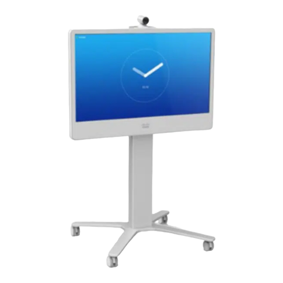
Installing Cisco TelePresence MX300 G2 - Wheel Base
78-100145-01 | OCTOBER 2013 | © 2013 Cisco Systems, Inc. All rights reserved.
This installation guide covers MX300 G2 with a wheel base.
Dimensions
Height: 1606 mm / 63.3 in.
Width: 1278 mm / 50.4 in.
Depth: 755 mm / 29.8 in.
Weight total: 47 kg / 104 lb
Weight monitor: 35 kg / 78 lb
Manpower
Two people working together are required to mount the
monitor to the base module.
Room setup
Explore the Meeting Room – London scenario on the Cisco Project
Workplace, http://www.cisco.com/go/projectworkplace, to find
inspiration and guidelines when preparing your office or meeting
room for video conferencing.
Documentation
The user documentation for this product, including compliance
and safety information, is available on the Cisco web site,
http://www.cisco.com/go/mx-docs
Advertisement
Table of Contents

Related Manuals for Cisco TelePresence MX300 G2


Summary of Contents for Cisco TelePresence MX300 G2
- Page 1 Documentation The user documentation for this product, including compliance and safety information, is available on the Cisco web site, http://www.cisco.com/go/mx-docs 78-100145-01 | OCTOBER 2013 | © 2013 Cisco Systems, Inc. All rights reserved.
- Page 2 • Microphones • Cables • Screws for mounting the monitor • Gloves Touch controller • Wheel base • Column • Screws for mounting the base • Screwdriver 78-100145-01 | OCTOBER 2013 | © 2013 Cisco Systems, Inc. All rights reserved.
- Page 3 M5x8 (Allen key, 3 mm) 4 × You may place the column on the empty wheel base box as illustrated. Then it is easier to enter the screws from below. 78-100145-01 | OCTOBER 2013 | © 2013 Cisco Systems, Inc. All rights reserved.
- Page 4 You need it in step 4. Front The monitor may be tilting slightly forward. If you gently pull it to a vertical position, the screws enter more easily. 78-100145-01 | OCTOBER 2013 | © 2013 Cisco Systems, Inc. All rights reserved.
- Page 5 Always use the provided power cable. with for the Touch controller; The wall socket outlet must be easily use the cable that is labeled with for the LAN accessible after installation. 78-100145-01 | OCTOBER 2013 | © 2013 Cisco Systems, Inc. All rights reserved.
- Page 6 Never move the camera manually when power is switched on; always use the camera control function on the Touch controller Lead the cables out at the to change the camera position. front or back as appropriate. 78-100145-01 | OCTOBER 2013 | © 2013 Cisco Systems, Inc. All rights reserved.
- Page 7 Cisco Systems, Inc. 170 West Tasman Dr. San Jose, CA 95134 USA Wind up the cables on the hook on the back cover when rolling the unit. 78-100145-01 | OCTOBER 2013 | © 2013 Cisco Systems, Inc. All rights reserved.
Need help?
Do you have a question about the TelePresence MX300 G2 and is the answer not in the manual?
Questions and answers