
Related Manuals for Hunter ROAM XL


Summary of Contents for Hunter ROAM XL
- Page 1 ROAM XL Commercial Remote Control ROAM XL Commercial Remote Control Owner’s Manual and Programming Instructions...
-
Page 2: Table Of Contents
InStALLAtIOnS ..... . .11 Receiver Mounted Indoors ROAM XL COMPOnEntS ......3 Receiver Mounted Outdoors TRANSMITTER MAXIMIzInG OPERAtInG RAnGE . - Page 3 CHAnGInG tHE RECEIVER AddRESS ...20 ACtIVAtInG A StAtIOn WItH tHE ROAM XL REMOtE SyStEM ....21 Activating a Program with the ROAM XL OPERAtInG RAnGE .
-
Page 4: Introduction
The large LCD display and simple five-button control start and stop a manual watering cycle when doing make the ROAM XL a snap to use. Simply press the maintenance or repair work on your irrigation system. keys to display the station or program you... -
Page 5: Roam Xl Components
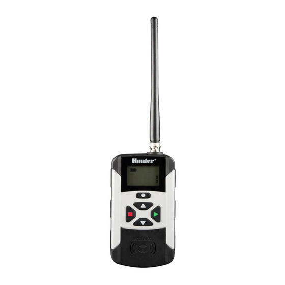
ROAM XL COMPONENTs SMARTPORT™ CARRyINg CASE TRANSMITTER RECEIVER... - Page 6 ROAM XL COMPONENTs This section will give you a brief description of the On – Indicates Transmitter is turning on the components that make up the ROAM XL. Each item selected station or program. Off – Indicates transmitter is turning off any will be discussed in further detail later.
-
Page 7: Receiver
– Turns off the selected functions. 14. SmartPort Outlet (female) – Outlet on front of ® SmartPort that plugs into the ROAM XL Receiver ® – Scrolls between functions, or access or other Hunter product. address screen. 15. Rubber Cover – Protects SmartPort from dirt ®... -
Page 8: Wiring Harness/Smartport
WIRING HARNEss/sMARTPORT CONNECTION KIT ® To use the ROAM XL Remote Control System, your controller must be equipped with the SmartPort ® wiring/harness connection kit. This wiring harness provides the connection port where the ROAM XL receiver is attached. The SmartPort wiring harness is included with the ®... -
Page 9: Wiring Harness
INsTALLING THE ROAM XL REMOTE WIRING HARNEss 1. Install a ½" female threaded “Tee” in the field wiring conduit approximately 12" (30 cm) from the controller. 2. Feed the red, white, and blue wires of the SmartPort through the base of the “Tee” and ®... - Page 10 INsTALLING THE ROAM XL REMOTE WIRING HARNEss 4. Route wiring harness into controller housing. nOtE: turn controller power off first, Attach the red wire to the first AC screw slot. before wiring the harness. Attach the white wire to the other AC screw slot, and attach the blue wire to the R (or REM on some controllers) as shown in Figure 2.
-
Page 11: Wiring The Smartport
WIRING THE sMARTPORT TO HuNTER CONTROLLERs ® sRC Controller smartPort Installation X-Core Controller smartPort Installation Access the terminal strip area and attach the red wire Access the terminal strip area and attach the red wire to the left AC screw slot, attach the white wire to the to the left side "24 VAC"... -
Page 12: Pro-C Controller Smartport Installation
AC screw slot and attach the blue wire to the screw slot marked “REM”. attach the blue wire to the screw slot marked “REM”. Blue Blue White White nOtE: Hunter ACC and I-Core controllers are provided with the SmartPort factory installed. ®... -
Page 13: Typical Installations
This installation is ideal for situations where a contractor desires the ability to access and operate a controller from outside of a locked building or garage. However, the ROAM XL receiver must be removed from the SmartPort and the weather ®... -
Page 14: Maximizing Operating Range
MAXIMIzING OPERATING RANGE There are many factors that influence operating range. Listed below are a few things you can do to assure that you get the maximum range possible. 1. Do not install the SmartPort near large metal ® objects such as power meters, water pipes, and aluminum siding. -
Page 15: Extending Wiring On Smartport ® Harness
The SmartPort should never be installed more than 15 m (50 ft.) metres away from the controller. BLUE BLUE For easiest installation, order a Hunter SRR-SCWH HUNTER SRR-SCWH WIRING HARNESS WHITE WHITE SmartPort wiring harness with a full 7.6 m (25 ft.) of ®... -
Page 16: Installing The Transmitter Batteries
INsTALLING THE TRANsMITTER BATTERIEs The ROAM XL transmitter requires 4 AAA alkaline batteries. To install the batteries, remove the two screws holding the battery on the back of the transmitter. Drop the batteries into the battery Remove these compartment and replace the door. your transmitter... -
Page 17: Station Run Time
CHANGING THE REMOTE ACTIVATEd sTATION RuN TIME Adjust the amount of time that a station will run 3. Use the buttons to change the Run before it has been turned on by your ROAM Time to any of the 10 settings ranging from 1 to XL System. -
Page 18: Changing The Transmitter Address
3. Use the buttons to change the your ROAM XL comes from the factory with both the address to any value between 0 and 127. Then Transmitter and the Receiver address set to 1. you do not touch any of the buttons for 5 seconds... -
Page 19: Changing The Maximum Number
CHANGING THE MAXIMuM NuMBER Of sTATIONs your ROAM XL transmitter has two operating modes, It is possible to switch the tranmitter between modes, Residential and Commercial (for ACC controllers). to operate residential controllers on certain sites, and These settings determine which controllers the ACC controllers on others. -
Page 20: Src/X-Core/Pro-C/Icc/I-Core
In residential mode, the maximum number of stations display appears. is from 1 to 48. The ROAM XL also provides the user with the ability to operate programs (A, B, C, D). 2. Press the Mode button three times, until the Station icon is displayed. -
Page 21: Preparing The Receiver For Use
PREPARING THE RECEIVER fOR usE your ROAM XL System is pre-addressed to work right out of the box. However, if you changed the Transmitter address as described in the section, Preparing the Transmitter For Use", you must allow the Receiver to learn the new address. -
Page 22: Changing The Receiver Address
3. Once the receiver beeps 4 times, you have Immediately after it beeps 4 times, approximately 7 seconds to send the new transmit with the ROAM XL to set the address to the receiver. Press either the new address. button on your transmitter to connect. -
Page 23: Roam Xl Remote System
ACTIVATING A sTATION WITH THE ROAM XL REMOTE sysTEM The ROAM XL System will allow you to remotely turn 4. Press the button to start the station or program. on and off any station on your Hunter controller with The Transmitter will display the Transmit icon . -
Page 24: Activating A Program With The Roam Xl
ACTIVATING A PROGRAM WITH THE ROAM XL REMOTE sysTEM Activating a Program with the ROAM XL nOtE: ROAM XL can activate any station on the residential controllers, you can maunally start a complete program in your regardless of whether the dial is in controller by selecting the applicable Program. - Page 25 ACTIVATING A sTATION WITH THE ROAM XL REMOTE sysTEM 3. Use the arrows to select the program you would like to start manually. 4. Press the button to send the signal to turn the controller On. The receiver will beep twice, and the Transmitter display will alternate between "On"...
-
Page 26: Operating Range
OPERATING RANGE ROAM XL has a maximum effective operating range of To insure optimum radio coverage: approximately 2 miles/3.5 km. • Replace the AAA batteries when the display “Maximum effective range” assumes level ground and indicates they are weakening, and keep spares on clear terrain. - Page 27 OPERATING RANGE • Do not modify the transmitter or receiver in any way! ROAM XL has been carefully designed to provide the best remote coverage possible within the regulations that govern wireless devices.
-
Page 28: Troubleshooting Guide
Replace lengthened wire with shielded cable ® controller is in the run position. and are receiving electrical or radio interference. to reduce radio interference. Use Hunter SRR-SCWH. See “Extending Wiring on SmartPort Harness.” ® Receiver does not receive signal from Mismatch of addresses in transmitter and Reset address of receiver. -
Page 29: Specifications
sPECIfICATIONs Operating specifications default settings • Address Range: 0–127 • Address: 1 • Maximum stations supported: 48 Residential • Number of Stations: 15 (may be varied from 1–240) Protocol, 240 Commercial Protocol • Run Time: 1 minutes • Run Time: 10 settings from 1–90 minutes dimensions • Range: up to 2 miles* (3 km*) Transmitter (w/o antenna): Height: 7"... -
Page 30: Notes
NOTEs... - Page 32 Hunter Industries Incorporated The Irrigation Innovators © 2012 Hunter Industries Incorporated • 1940 Diamond Street San Marcos, California 92078 USA LIT-586 6/12 • www.hunterindustries.com...
Need help?
Do you have a question about the ROAM XL and is the answer not in the manual?
Questions and answers