Table of Contents
Advertisement
Quick Links
Residential/Light Commercial
Residential/Light Commercial
Remote Control System
Remote Control System
Owner's Manual and
Owner's Manual and
Installation Instructions
Installation Instructions
For use with Hunter Controllers
For use with Hunter Controllers
with SmartPort
with SmartPort
Connection
®
Connection
®
Advertisement
Table of Contents

Related Manuals for Hunter Roam


Summary of Contents for Hunter Roam
- Page 1 Residential/Light Commercial Residential/Light Commercial Remote Control System Remote Control System Owner’s Manual and Owner’s Manual and Installation Instructions Installation Instructions For use with Hunter Controllers For use with Hunter Controllers with SmartPort Connection ® with SmartPort Connection ®...
-
Page 3: Table Of Contents
INTRODUCTION ............................1 ROAM COMPONENTS ..........................2 WIRING HARNESS/SMARTPORT CONNECTION KIT .................. 5 ® INSTALLING THE ROAM REMOTE WIRING HARNESS ................. 6 WIRING THE SMARTPORT TO HUNTER CONTROLLERS ................7 ® TYPICAL INSTALLATION ........................... 8 MAXIMIZING OPERATING RANGE ......................9 EXTENDING WIRING ON SMARTPORT HARNESS .................. - Page 4 CHANGING THE MAXIMUM STATION NUMBER ..................15 PREPARING THE RECEIVER FOR USE ......................16 CHANGING THE RECEIVER ADDRESS ......................17 ACTIVATING A STATION WITH THE ROAM REMOTE CONTROL SYSTEM ............18 A WORD ABOUT RANGE ........................... 19 TROUBLESHOOTING GUIDE ........................20 SPECIFICATIONS ............................
-
Page 5: Introduction
AAA alkaline batteries will last an entire season for a contractor, and years for a homeowner. We believe the ROAM is the simplest remote control available. It is so easy to use that you will need this booklet very little after installation. If you do have a question, keep this in a safe place for easy reference. -
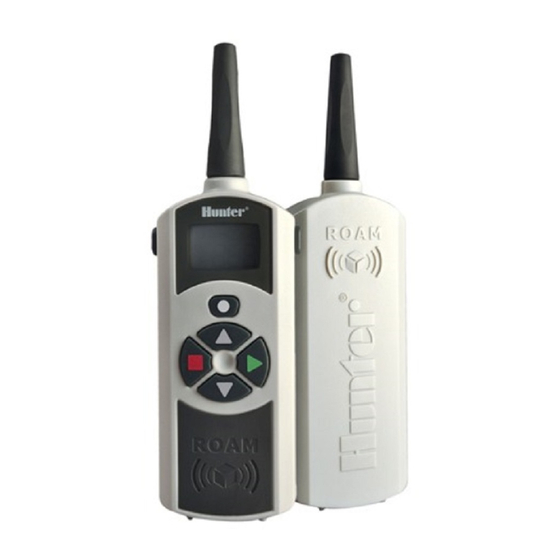
Page 6: Roam Components
RoaM CoMPonenTs ................ TRANSMITTER RECEIVER SmartPort ®... - Page 7 This section will give you a brief description of B. Control Buttons the components of the ROAM. Each item will be – Increases the selected functions. discussed in further detail later, however this – Decreases the selected functions. section can be helpful in getting acquainted with the Transmitter, Receiver, and SmartPort ®...
- Page 8 1000' (305 m). SmartPort ® 13. SmartPort Outlet (Female) – Outlet on ® front of SmartPort that plugs into the ROAM ® Receiver or other Hunter product. 14. Rubber Cover – Protects SmartPort from dirt ® and weather.
-
Page 9: Wiring Harness/Smartport ® Connection Kit
WiRinG HaRness/sMaRTPoRT ConneCTion KiT ....® To utilize the ROAM Remote Control System, your controller must be equipped with the SmartPort ® wiring/harness connection kit. This wiring harness provides the connection port where the ROAM receiver is attached. The SmartPort wiring harness is included with ®... -
Page 10: Installing The Roam Remote Wiring Harness
THe RoaM ReMoTe WiRinG HaRness ....NOTE: Any extension of the wires NOTE: While the SmartPort has a ® provided with the standard wiring protective cover to allow for outdoor harness may result in an error installation, the ROAM Receiver... -
Page 11: Wiring The Smartport ® To Hunter Controllers
WiRinG THe sMaRTPoRT To HunTeR ConTRolleRs ..® SRC Controller SmartPort Installation ICC Controller SmartPort Installation ® ® Access the terminal strip area and attach the red wire Access the terminal strip area on the power module to the left AC screw slot, attach the white wire to the... -
Page 12: Typical Installation
Receiver Mounted Indoors To Controller This installation is ideal for situations when the ROAM system will be left permanently connected to the controller in an indoor area. Connection of Receiver on a Temporary Basis from Outside of a Garage or Building... -
Page 13: Maximizing Operating Range
MaXiMiZinG oPeRaTinG RanGe ..........There are many factors which influence operating NOTE: Remote is designed for range. Listed below are a few things you can do to residential and small commercial assure that you get maximum range possible. sites. Large projects such as cemeteries and golf courses will 1. -
Page 14: Extending Wiring On Smartport ® Harness
15 meters away from the controller. BLUE BLUE HUNTER SRR-SCWH WIRING HARNESS WHITE WHITE For easiest installation, order a Hunter SRS-SCWH SmartPort wiring harness with a full 7.6 meters of ® shielded cable. SRC TERMINAL BLOCK PRO-C TERMINAL BLOCK... -
Page 15: Preparing The Transmitter For Use
PRePaRinG THe TRansMiTTeR foR use ........Your ROAM System is designed to work right out of the box. This means that other than installing the batteries, you may choose to skip this entire section. However, we recommend you read it because with a few simple steps you can customize your ROAM to add functionality and security to your system. -
Page 16: Installing The Transmitter Battery
THe TRansMiTTeR baTTeRY ........ Your ROAM Transmitter requires four AAA alkaline batteries. To install the batteries, slide open the battery door on the back of the transmitter. When changing the batteries, make sure that they are oriented properly in the battery holder. Slide the... -
Page 17: Changing The Remote Activated Station Run Time
You have the ability to adjust the amount of time that a station will run once it has been turned on by your ROAM System. This does not affect the run time programmed into your controller. There are 10 preset run times from 1 minute to 90 minutes. -
Page 18: Changing The Transmitter Address
0 and 127. Then do not touch any of the buttons for 10 seconds Your ROAM comes from the factory with both the and the display will return back to the active Transmitter and the Receiver address set to 1. You station. -
Page 19: Changing The Maximum Station Number
9 stations. In this case you would want to access the stations above 9. Caution: If MAX station is set to 240, ROAM will only work with the ACC controller. If you are using an SRC, Pro-C, or ICC controller, make sure your station count is set to 1 - 48. -
Page 20: Preparing The Receiver For Use
PRePaRinG THe ReCeiVeR foR use ..........As stated earlier, your ROAM System is designed to work right out of the box. If you have decided to change your Transmitter address as described in the previous section, you must allow the Receiver to “learn”... -
Page 21: Changing The Receiver Address
CHanGinG THe ReCeiVeR addRess ..........1. Before setting the receiver address, make sure that the transmitter address is set to the address you would like to use. 2. Plug the receiver into a SmartPort connected ® to a powered controller. When this is done, the receiver will beep 4 times. -
Page 22: Activating A Station With The Roam Remote Control System
WiTH THe RoaM ReMoTe ConTRol sYsTeM ................The ROAM System will allow you to remotely turn 5. Press the button to turn off any station that is on and off any station on your Hunter controller with on. -
Page 23: A Word About Range
Furthermore, it has special circuitry to assure that for that matter. The published range for the ROAM this maximum output power is maintained until just System is up to 1000' (305 m). Most users will before the battery goes dead. -
Page 24: Troubleshooting Guide
Replace lengthened wire with shielded cable to ® display when controller is in the receiving radio interference. prohibit radio interference. Use Hunter ROAM-SCWH. run position. See “Extending Wiring on SmartPort Harness.” ® Receiver does not receive signal Mismatch of addresses in transmitter and receiver. -
Page 25: Specifications
sPeCifiCaTions ................Operating Specifications Default Settings • Address range: 0-127 • Address = 1 • Maximum stations supported: 240 • Number of stations = 15 (may be varied from 1-240) • Run Time: 10 settings from 1-90 minutes • Run Time: 2 minutes • Range: up to 1,000 ft* (305 m*) Dimensions Electrical Specifications Transmitter: Receiver: • Power Source Transmitter: • Height: 7" (17.8 cm) • Height: 7” (17.8 cm) (4) AAA Alkaline Batteries •... -
Page 26: Notes
fCC noTiCe ..................Transmitter FCC ID:M3URMT This device complies with FCC rules Part 15. Operation is subject to the following two conditions: 1. This device may not cause harmful interference and 2. This device must accept any interference received, including interference that may cause undesired operation. This equipment has been tested and found to comply with the limits for class B digital devices, pursuant to part 15 of the FCC Rules. -
Page 27: Fcc Declaration Of Conformity
COMPLIANCE TEST REPORT NUMBER B80912D1 COMPLIANCE TEST REPORT DATE Sept 12th, 2008 RESPONSIBLE PARTY Hunter Industries Incorporated ADDRESS 1940 Diamond St, San Marcos CA 92078 TELEPHONE 760-744-5240 This equipment has been tested and found to comply with the limits for class B digital devices, pursuant to part 15 of the FCC Rules. -
Page 28: Fcc Compliance Notice
Ce & ausTRalia noTiCe ..........Hunter Industries hereby declares that this remote control device is in compliance with the essential requirements and other relevant provisions of Directive 1999/5/CE. Declaration of Conformity: We, Hunter Industries Incorporated, 1940 Diamond Street, San Marcos, CA 92078, declare under our own...
Need help?
Do you have a question about the Roam and is the answer not in the manual?
Questions and answers
I have 12 stations, my Roam TX shows 1 - 7, then shows PA, Pb, PC, and Pd. It does not show stations 8-12
on the first three stations the run time works on the second three stations only the three minimum time runs