Advertisement
Quick Links
Advertisement

Related Manuals for DOEPFER LMK4+


Summary of Contents for DOEPFER LMK4+
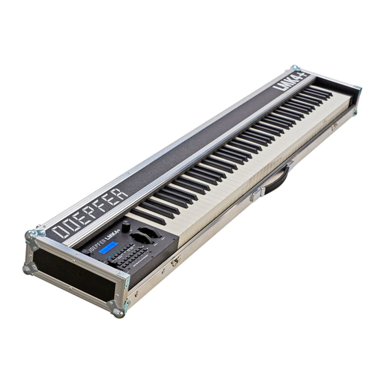
- Page 1 DOEPFER MIDI Master Keyboard LMK4+ LMK4+ LMK4+ LMK4+ User's Guide...
- Page 2 User's Guide LMK4+ INDEX Operation (Hardware) Power Supply MIDI-Interface Connection of External Controllers and Footswitches Controls Operating and Security Instructions Operation (Software) Switching the keyboard ON Menu Structure Description of Menus 2.3.1 Preset 2.3.2 Program Change / Bank Select 2.3.3 Real Time / Master Channel 2.3.4 Split...
-
Page 3: Operation (Hardware)
The foot switches and foot controllers are not included with the LMK4+ and have to be ordered separately if required. A suitable foot switch is the DOEPFER VFP2, a suitable foot controller is the DOEPFER FP5. The LMK4+ will work without the foot switches and foot controllers, although the corresponding functions will not be available to the user in that case. - Page 4 For details regarding assignment of MIDI functions to the foot controllers (e.g. volume, sustain, soft pedal and so on) refer to chapter 2.3.5 Controller Assign / Activate. 1.4 Controls The LMK4+ features the following controls and displays: • Illuminated display with two rows of 16 characters each •...
-
Page 5: Operating And Safety Instructions
1.5 Operating and Safety Instructions Please follow the given instructions for use of the instrument because this will guarantee correct instrument operation. Due to the fact that these instructions touch on Product Liability, it is absolutely imperative that they be read carefully. -
Page 6: Operation (Software)
2. OPERATION (Software) 2.1 Switching the Keyboard ON When the keyboard is switched ON a message regarding the software version will appear on the display for several seconds (e.g. "LMK4 V1.00"). In addition the LED's will flicker for several seconds. After that the keyboard will go into preset-mode (see below for details) and will call up preset no. - Page 7 4: SPLIT The LMK4+ handles up to 8 different keyboard areas (split areas, split zones, split range) simultaneously. Overlaps of the zones are possible (i.e. some keys are used by more than one zone). Each zone is assigned a MIDI channel and to one of the 2 MIDI outputs. The SPLIT-menu is used to define the parameters of each of the 8 keyboard zones.
-
Page 8: Detailed Description Of Menus
2.3 DETAILED DESCRIPTION OF MENUS 2.3.1 Preset (1) This menu is entered by pressing the leftmost MENU-button. Switching the keyboard ON will also activate this menu. It serves to call up and store presets. A preset is the sum of all information defining a keyboard configuration. - Page 9 Storing a Preset The data of the work-memory can be stored via the PRESET-menu. It can be placed in one of the 128 preset-memory locations by pressing the PRESET-menu-key and the PANIC-menu-key (first and last menu- button) simultaneously. The following message appears on the display: STORE MODE OK? Also, all 8 LED's will be illuminated as a warning! Next the desired BANK-button and possibly the PRESET-menu- button (to alter the range 0...64/65...128) to be pressed, followed by a NUMBER-button.
- Page 10 64 apears. The System Exclusive specification of the LMK4+ is available free of charge from our internet pages (www.doepfer.com) or in printed form if you send us 5 international reply coupons. 2.3.2 Program Change / Bank Select (2) This menu is called up by pressing the second MENU-button from the left.
- Page 11 devices connected to LMK4+ if the bank message is supported and which values for Controller #0/32 are used. Normally only a few combinations of controller #0 and #32 are allowed to select one of the program banks availabe. Some manufacturers also use only Controller #0 or #32 to select a program bank. Other manufacturers designate this function as page, page select or variation.
- Page 12 YYYYYYY is one of the following 4 choices that can be adjusted together with the MIDI-master-channel XX via the rotary encoder: POUT1&2 external Preset call-up active / Outputs 1&2 POUT1&0 external Preset call-up active / Output 1 POUT0&2 external Preset call-up active / Output 2 OUT1&2 external Preset call-up turned off / Output 1&2 In case of POUT...
- Page 13 MIDI messages as the incoming MIDI data has to be merged with the MIDI data of the LMK4+. For such applications an external MIDI-merger (like the DOEPFER MMR4/4) should be used. Moreover one has to consider that incoming MIDI data may be multliplied by a factor 8 if the MIDI input is routet to all zones. If there is alreadya considerable data rate on the input the maximum tranfer limit of MIDI may be exceeded at the output(s)..
- Page 14 If the display shows the message "STORE" on the upper right when the PROGRAM/BANK-button is pressed, then the function in question is presently activated. This means that the program-number and bank-numbers entered will be stored in the preset and will be sent when the preset is called up (see Menu 1: PRESET). If this is not desired in a given keyboard zone, then the function can be disabled by pressing the PROGRAM/BANK-button once more.
- Page 15 2.3.5 Controller Assign/Activate (5) This menu is selected by pressing the fifth MENU-button from the left. The menu has 2 functions. The first is the assignment of controllers to the standard MIDI-functions ("Assign"- function). The second is the activation of the controllers in the various keyboard zones ("Activate"-function). When entering this menu one reaches the "Activate"-portion first.
- Page 16 The following standard MIDI-functions can be assigned to the various controllers (with abbreviations): Pitch Bend Portamento Aftertouch Data Entry Modulation Volume Breadth-Controller Panorama In addition there are 8 user-defined controllers (UD1...UD8) which are explained in section 2.3.6. The assignment of the selected controller to a MIDI-function is accomplished by turning the data-entry dial. The assigned function will appear in the display to the right of the arrow symbol (in abbreviated form).
- Page 17 A special case is the assignment of of the after-touch-sensor to pitch-bend. There is a global parameter in menu 7 (PARAMETERS), called ATP (Aftertouch-to-Pitch) which determines whether the pressure exerted on the keys has a positive or negative effect on pitch-bend. Without pressure the pitch-bend value of 64 is sent ($40 Hexadecimal).
- Page 18 the preset presently active (see CONTROLLER ASSIGN/ACTIVATE for details). When the switch is pressed the following message will appear on the display: LINK TO PRES > YYY YYY is the number of the next preset activated when presets are switched over. The number is set to the desired value via the data-entry dial.
- Page 19 global, i.e. once set it is valid for all presets stored in the LMK4+. Of course the parameter is meaningful only if the aftertouch sensor has been assigned to the pitch-bend function. The last BANK-button triggers the Memory transfer from volatile to the non-volatile part after a receive dump. Before the transfer is performed the following message appears in the display: STORE ALL PRE- SETS TO EEPROM?
- Page 20 APPENDIX A: Explanation of the velocity-response curves and aftertouch curves. When defining the parameters of the keyboard zones one can select among 64 velocity-response curves and 8 aftertouch curves. In the following paragraph the reasons for this feature shall be discussed briefly. The special MIDI-chip used inside the LMK2 to poll the key-contacts uses the time difference required by the switch-contact to derive the velocity response (or dynamics-value).
- Page 21 VELOCITY-RESPONSE CURVES AFTERTOUCH-RESPONSE CURVES LMK4+ User's Guide Page 21...
- Page 22 Appendix B: Pin Assignment of the Jack Sockets Power Supply 1 = +7...12V DC 2 = GND "high" "low" Foot Controller (EXT.CTRL. 1/2) 2...10k linear Foot Switches (SWITCHES) Switch 2 Switch 1 Appendix C: Conversion table Bank/Numbers to Decimal System LMK4+ User's Guide Page 22...
- Page 23 Appendix D: Quick reference table of functions LMK4+ User's Guide Page 23...
- Page 24 Appendix E: Initialization of the LMK4+ One must operate the two right-hand menu buttons PARAM.NAME and PANIC simultaneously for several seconds while connecting the power supply. Then the message "EEPROM-SETUP" appears in the upper line of the display. Operating the first menu button (PRESET) starts the set-up routinees and the message in the display changes to "INIT PRESETS".
Need help?
Do you have a question about the LMK4+ and is the answer not in the manual?
Questions and answers