Table of Contents
Advertisement
Advertisement
Table of Contents

Related Manuals for Star Micronics TSP650II SERIES


Summary of Contents for Star Micronics TSP650II SERIES
- Page 1 THERMAL PRINTER 650 II SERIES Hardware Manual...
- Page 2 Federal Communications Commission Radio Frequency Interference Statement This device complies with Part 15 of the FCC Rules. Operation is subject to the following two conditions: (1) This device may not cause harmful interference, and (2) this device must accept any interference received, including interference that may cause undesired operation. NOTE: This equipment has been tested and found to comply with the limits for a Class A digital device, pursuant to Part 15 of the FCC Rules.
-
Page 3: Trademark Acknowledgments
This statement will be applied only for the printers marketed in U.S.A and Canada. CE MARKING WARNING Hereby, Star Micronics Co., Ltd. declares that this device is in compliance with the essential requirements and other relevant provisions of Directive 1999/5/EC. -
Page 4: Table Of Contents
TABLE OF CONTENTS 1. Unpacking and Installation ................. 1 1-1. Unpacking ....................1 1-2. Notes about Installation ................1 2. Parts Identification and Nomenclature ............2 3. Setup ......................3 3-1. Connecting the Interface Cable to the PC ............3 3-2. -
Page 5: Unpacking And Installation
1. Unpacking and Installation 1-1. Unpacking After unpacking the unit, check that all the necessary accessories are included in the package. Paper roll Paper roll guide CD-ROM Safety Instruction & Setup sheet Printer Switch blind Rubber feet Screws Holding plate * Accessories vary depending on the model and the region where the printer was purchased. -
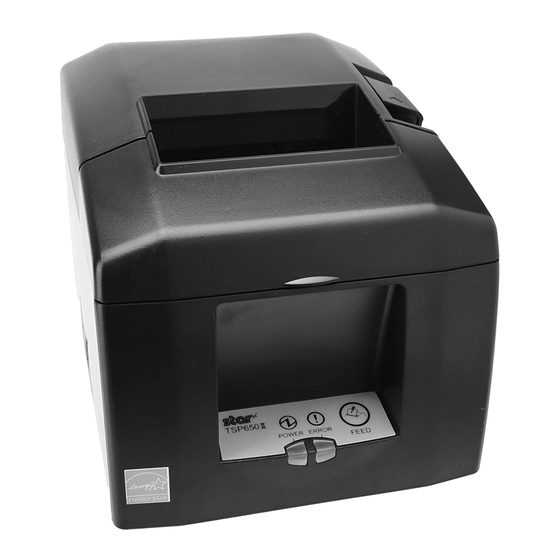
Page 6: Parts Identification And Nomenclature
2. Parts Identification and Nomenclature Printer cover Cover open lever Open to replace paper. Use this lever to open the Do not open while printing. printer cover. Power switch Control panel Turns the printer on Features lamps that indicate printer and off. -
Page 7: Setup
3. Setup 3-1. Connecting the Interface Cable to the PC 3-1-1. Parallel Cable Connect the parallel cable to a parallel port on your PC. 3-1-2. RS-232C Cable Connect the RS-232C cable to a RS-232C port on your PC. 3-1-3. USB Cable Connect the USB cable to a USB port on your PC. -
Page 8: Connecting The Interface Cable To The Printer
3-2. Connecting the Interface Cable to the Printer Printer cables are not included in the package. Obtain an appropriate cable that complies with the specifications beforehand. Because the appropriate interface cable differs depending on the system that you are connecting the printer to, contact the dealer that you bought the product from if you are unsure about what cable to use. -
Page 9: Usb Cable
3-2-2. RS-232C Interface Cable (1) Make sure that the AC adapter’s power cord is not connected to the outlet. (2) Connect the interface cable to the connector on the rear panel of the printer. (3) Tighten the connector screws. RS-232C interface cable 3-2-3. -
Page 10: Ethernet Cable
3-2-4. Ethernet Cable To connect the cable, follow the procedure given below. (1) Make sure that the AC adapter’s power cord is not connected to the outlet. (2) Connect the Ethernet cable to the Ethernet port. Ethernet cable IFBD-HE07 Link disconnection detection feature The Ethernet interface model is equipped with a link disconnection detection feature. -
Page 11: Connecting The Ac Adapter
3-3. Connecting the AC Adapter Note: Before connecting or disconnecting the AC adapter, make sure that the printer and all the devices connected to it are turned off. Then remove the power cord from the outlet. (1) Connect the AC adapter to the power cord. (2) Connect the AC adapter to the connector on the printer. -
Page 12: Turning The Power On
3-4. Turning the Power On Connect the power cord according to the procedure in section 3-3, “Connecting the AC Adapter”. Turn on the power switch, which is on the left side of the printer. The POWER lamp on the control panel will light. Power switch 3-5. -
Page 13: Loading A Paper Roll
3-6. Loading a Paper Roll Use a paper roll that complies with the printer specifications. (1) Push the cover open lever, and open the printer cover. Cover open lever (2) Load the paper roll into the printer in the direction indicated by the figure, and pull the leading edge of the paper straight toward you. - Page 14 3-6-1. Compliant Paper Roll Specifications 53 μm to 85 μm Paper thickness 79.5 ± 0.5 mm Paper width 57.5 ± 0.5 mm External dimensions Max. f 83 mm • Roll diameter • Take up paper roll width +0.5 +0.5 mm / 58 Inner diameter f 12 ± 1 mm, external diameter f 18 ± 1 mm Core inner and outer diameters Printed surface Outer edge of roll...
-
Page 15: Changing The Paper Width
3-6-2. Changing the Paper Width When using 57.5 mm width paper rolls, attach the supplied paper roll guide to the printer. When you change the effective print width (paper roll width), change the printer utility’s memory switch setting. For details, see the printer utility help. (1) Insert the paper roll guide firmly into the slot in the printer labeled "r58"... -
Page 16: Bluetooth Setting (For Bluetooth Interface Model Only)
(2) Pairing will be possible for 60 seconds from when the LED begins flashing green. During this time, perform pairing from the master device. Device name: Star Micronics (default) (3) After performing pairing, wait until the LED stops flashing green, or turn the printer off and back on again, to enable the connection. - Page 17 Enter the following information in the master device if it does not support SSP, or when otherwise necessary. PIN: 1234 (default) Device name: Star Micronics (default) It is recommended that you change the PIN code for greater security. For details regard changing the PIN code, please see the “Bluetooth Utility Software Manual”.
- Page 18 3-7-4. Resetting Bluetooth Settings The PIN code, device name, and other settings can be reset by following the procedure given below. (1) Use a fine pointed pen or other similar object to press and hold the RST button. While holding the RST button, turn the printer's power switch on.
-
Page 19: Setup Precautions
3-8. Setup Precautions Caution Symbol These symbols are located near the thermal print head. Because the thermal print head is hot immediately after printing, do not touch it. Static electricity can damage the thermal print head. To protect the thermal print head from static electricity, do not touch it. -
Page 20: Wireless Communication
Below is a list of laws this device has been approved by. As Star Micronics is committed to constant innovation, revi- sions may be made without an announcement. Access the Star Micronics website for the latest listing of approvals. -
Page 21: Attaching The Accessories
4. Attaching the Accessories The following accessories are necessary when mounting the printer to a wall. • Holder plate and two flangeless screws The following accessories are necessary when positioning the printer vertically. • Four rubber feet The following accessories do not necessarily have to be attached. Attach it if necessary. •... - Page 22 (3) Push the cover open lever, and open the printer cover. (4) Insert the roll paper as shown. Precautions regarding installation CAUTION This caution indicates information that, if ignored, could lead to personal injury or property damage. • Be sure to have qualified personnel install the specified screws and printer to the wall.
-
Page 23: Attaching The Rubber Feet
4-2. Attaching the Rubber Feet (1) Ensure that any soiling has been completely wiped off before attaching the rubber feet. (2) Attach the four rubber feet in the positions shown in the figure. 4-3. Switch Cover Installation It is not necessary to install the switch cover. Only install it if it is necessary for you. By installing the switch cover, the following become possible. -
Page 24: Adjusting The Near-End Sensor
5. Adjusting the Near-end Sensor Use the following procedure to adjust the near-end sensor so it is compatible with the size of paper roll you are using. Adjustment value according to the paper you are using Horizontal (standard) Layout Vertical Layout or Wall-Mount ø12 inner diameter / ø18 outer diameter core roll paper ø12 inner diameter / ø18 outer diameter core roll paper Paper Width... -
Page 25: Error Indicators
6. Error Indicators 6-1. Recoverable errors Check the recovery conditions. The printer can be recovered while maintaining its current status. Error description POWER ERROR Recovery condition Thermal head high Flashes at 1 sec- temperature detection The printer recovers automatically when the thermal head cools. ond intervals error Cover open error... -
Page 26: Preventing And Removing Paper Jams
7. Preventing and Removing Paper Jams 7-1. Preventing Paper Jams To avoid paper jams and other problems, feed the paper at least 1 mm (8 dot lines) before printing. If you want to use the cutter, to avoid paper jams and other problems, we recommend a margin of at least 5 mm from the end of the printed area to the cutting position. -
Page 27: Releasing The Cutter Lock
7-3. Releasing the Cutter Lock If the auto cutter locks up, restart the printer by turning the power switch off and then back on. A typical locked cutter will be restored when you restart the printer. If restarting the printer does not release the locked cutter, follow the procedure below. Note 1: Be sure to turn off the printer before performing maintenance on the cutter. -
Page 28: Maintenance
8. Maintenance Accumulation of paper dust and dirt may cause the printer to not print portions of characters. To prevent such problems, perform periodic maintenance, such as removing paper dust from the paper transport sec- tion and removing the blackened paper dust from the thermal head surface. As a guideline, clean the printer every six months. -
Page 29: Declaration Of Conformity
Manufacturer’s Name Star Micronics Co.,Ltd. Manufacturer’s Address 20-10 Nakayoshida, Suruga-ku, Shizuoka-shi, Shizuoka 422-8654 Japan Importer’s Name Star Micronics Europe Ltd. Importer’s Address Star House, Peregrine Business Park, Gomm Road, High Wycombe, Bucks. HP13 7DL, U.K. Type of Equipment Thermal Printer... - Page 30 http://www.starmicronics.com/support/...
Need help?
Do you have a question about the TSP650II SERIES and is the answer not in the manual?
Questions and answers