
Related Manuals for Broan Elite 15SSEXF


Summary of Contents for Broan Elite 15SSEXF
- Page 1 Service Manual Trash Compactor Models 15SSEXF • 15BLEXF 99044662A November 2010 Broan-NuTone LLC • 926 West State Street • Hartford, WI 53027 • 1-800-637-1453...
-
Page 2: Safe Servicing Practices
This service manual is intended for use by persons having electrical and mechanical training and a level of knowledge of these subjects considered acceptable in the appliance repair trade. Broan- NuTone cannot be responsible, or assume any liability, for injury or damage of any kind arising from the use of this manual. -
Page 3: Table Of Contents
Table of Contents Table of contents Section D – Electrical Components .......... Start Switch .................. Remove and Replace .............. Access to Components ..............Safe Servicing Practices ............Remove Cabinet Cover ............Grounding Instructions .............. Re-install Cabinet Cover ............Control Panel Assembly ............... Features .................. -
Page 4: Features
Features ELECTRICAL COMPONENTS (SECTION D) POWER UNIT MECHANISM (SECTION C) CABINET (SECTION B) How the compactor works The compactor compresses household trash up to 1/6 of its original volume. It will compact normal household trash including milk cartons, glass and plastic bottles, containers and jars, tin cans, wrappings, boxes, food wastes, etc. When you start the compactor, an electrically powered ram moves down into the trash bucket, compresses the trash and then returns to the “UP”... -
Page 5: Section A - Installation
Section A – Installation Built-in Installation Your compactor has been designed to require minimum space without loss of capacity whether free-standing or built-in. MOUNTINg STRAPS Free-Standing TOP OF COMPACTOR As shipped, the compactor is only configured for built-in installations. This appliance can be converted from built- in to free-standing with the use of Toe Kick Accessory Kit Model 15TCTK (sold separately). -
Page 6: Cord Clamp
Section A – Installation Leveling the Compactor CORD CLAMP The compactor is equipped with a 6-ft. long power cord. Your compactor has four adjustable levelers; (2) rollers in Use the cord clamp to prevent excess power cord from the rear and (2) legs in the front. They allow you to adjust being pinched beneath the cabinet during installation or for uneven floors and also trim the unit up to fit an under- service. -
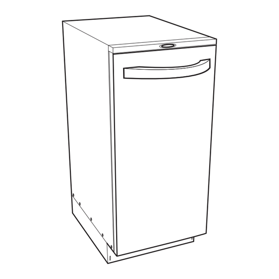
Page 7: Section B - Cabinet
Section B – Cabinet C, D Cabinet Legend The compactor’s main cabinet supports and encloses Trash Bucket a number of sub-assemblies. These include the trash Bucket Handle bucket, the door, the motor, the ram, and the electrical C, D. Slide Rails controls and components. -
Page 8: Trash Bucket
Section B – Cabinet Trash Bucket Bucket Handle REMOvE REMOvE AND REPLACE To remove the bucket completely from the cabinet for The plastic bucket handle may receive a lot of “wear and repairs or cleaning, follow these instructions. tear” simply because the operator uses it every time he or she places trash into the compactor, or removes or replaces the bag. -
Page 9: Slide Rails (Cabinet)
Section B – Cabinet Slide Rails (Cabinet) Slide Rails (Bucket) REMOvE AND RE-INSTALL REMOvE AND RE-INSTALL The compactor’s slide rails may become bent from mis- use or the ball bearings may become worn. RAIL SCREW BUCKET SPRING CLIPS SCREW RAIL SCREWS Remove four Phillips head screws that secure the left slide rail to the bucket. -
Page 10: Door Assembly
Section B – Cabinet Door Assembly REvERSE DOOR HINgE POSITION The compactor comes from the factory with the door REMOvE AND RE-INSTALL in the right-hand opening position. Use the following instructions to reverse the door. The heavy-duty door could become dented, scratched Remove the door (see Remove and Re-install). -
Page 11: Safety Interlock Actuator
Section B – Cabinet Safety Interlock Actuator TRIM PIECE REMOvE AND RE-INSTALL This safety device prevents the compactor from operating UPPER except when the door is closed. NOTE: If the interlock HINGE actuator should break off, the compactor will not function; replace it promptly. -
Page 12: Gasket Assembly
Section B – Cabinet Gasket Assembly Remove door assembly (see Door Assembly, Remove and Re-install). REMOvE AND RE-INSTALL Remove control panel (see Electrical Components, Control Panel Assembly). The gasket is made of a flexible vinyl material with imbedded magnets. Over time it may become brittle or cracked, and lose its flexibility. -
Page 13: Top Trim Cover Assembly
Section B – Cabinet Top Trim Cover Assembly REMOvE AND RE-INSTALL Remove the door (see Door Assembly, Remove and Re-install). SCREWS Remove the four Phillips head screws that secure the top trim cover to the cabinet. Pull the top trim cover away from the cabinet. Re-install in reverse order. -
Page 14: Section C - Power Unit Mechanism
Section C – Power Unit Mechanism Legend A. Drive Belt B. Main Motor C. Complete Power Unit Mechanism D. Ram Screw Assembly... -
Page 15: Drive Belt
Section C – Power Unit Mechanism Drive Belt DRIVE WHEELS REMOvE AND RE-INSTALL The drive belt transfers power from the motor to the ram screws. If it requires replacement, follow these steps. 4 COVER BELT SCREWS COVER CAP SCREWS BELT Use a 5 mm hex wrench to loosen the three hex head cap screws. -
Page 16: Main Motor
Section C – Power Unit Mechanism Main Motor REMOvE AND REPLACE Follow these instructions if it becomes necessary to replace the main motor. DRIVE WHEEL IDLER WHEEL MOTOR 3 HEAD CAP SCREWS, IDLER LOCK WASHERS AND WHEEL FLAT WASHERS NOTE: For illustration purposes, the view is shown with the drive wheels removed. -
Page 17: Complete Power Unit Mechanism
Section C – Power Unit Mechanism Complete Power Unit Drive Wheels Mechanism REMOvE AND REPLACE REMOvE AND RE-INSTALL SPRING WASHER The complete power unit mechanism consists of the ram screw assemblies, the motor and the drive belt. Rather BEARING than replace individual components, it may be easiest to replace the whole mechanism. -
Page 18: Ram Screw Assembly
Section C – Power Unit Mechanism Ram Screw Assembly REMOvE AND REPLACE The ram screw assemblies transfer power to the ram and plate. Heavy usage can damage the threaded rod. If it becomes necessary to replace one or both of the ram screw assemblies, follow the instructions below. - Page 19 Section C – Power Unit Mechanism FASTENERS SLOT FASTENERS Turn the ram until the top pin indexes 90° from the pin slot; remove two hex screws, lock washers and flat washers (fasteners). Remove two hex head screws, shims, brackets and nuts (fasteners) from the top of the ram screw Turn the ram as required to align the ram pin with the assembly.
- Page 20 Section C – Power Unit Mechanism THRUST WASHER BEARING BEARING HOUSING THRUST BEARING BEARING WASHER HOUSING Remove the pin, thrust washer, bearing, and upper bearing housing from the ram. SCREW Lower the ram screw assembly through the center stabilizer plate. STABILIzER PLATE SCREW...
-
Page 21: Section D - Electrical Components
Section D – Electrical Components H, I Legend A. Cabinet Cover B. Control Panel Assembly C. Display Module Assembly D. Cabinet Safety Interlock Switch E. Key Switch Assembly F. Upper Limit Switch Assembly G. Lower Limit Switch H. Motor Centrifugal Switch Assembly Motor Capacitor j. -
Page 22: Start Switch
Section D – Electrical Components Start Switch Access to Components REMOvE AND REPLACE In order to access the electrical components, it is first necessary to remove the cabinet cover. The start switch is located inside of the cabinet, behind REMOvE CABINET COvER the push button assembly. - Page 23 Section D – Electrical Components Remove control panel assembly (see Control Panel Assembly, Remove and Re-install). SCREWS Remove six Phillips head screws each that secure the front and rear of the stabilizer plates to the cabinet cover (rear view shown). NOTCH SCREWS NOTCH...
-
Page 24: Re-Install Cabinet Cover
Section D – Electrical Components RE-INSTALL CABINET COvER SCREWS PINS Remove five Phillips head screws each from the lower right and left sides of the cabinet cover. 1. To re-install the cabinet cover, lift the cover over the top of the unit and allow it to rest temporarily on the top of the locator pins. -
Page 25: Control Panel Assembly
Section D – Electrical Components Control Panel Assembly WIRING HARNESSES REMOvE AND RE-INSTALL The control panel assembly houses the display panel, the safety interlock switch, the bag storage, and the odor control disk tray. SCREWS After removing these five screws, open odor disk tray, pull the panel away from the cabinet and disconnect the two wiring harnesses. -
Page 26: Display Module Assembly
Section D – Electrical Components Display Module Assembly Key Switch REMOvE AND RE-INSTALL REMOvE AND REPLACE The display module assembly contains switches that allow the operator to turn the compactor ON and OFF and to CONTROL select HOLD or NORMAL mode. PANEL INTERLOCK Remove the control panel assembly from the unit (see... -
Page 27: Interlock Switch Assembly
Section D – Electrical Components Interlock Switch Assembly Upper Limit Switch Assembly REMOvE AND RE-INSTALL REMOvE AND REPLACE The interlock switch assembly is a safety feature. The This switch sets the upper travel limit for the ram switch prevents the compactor from operating unless the mechanism. -
Page 28: Lower Limit Switch
Section D – Electrical Components Lower Limit Switch Motor Centrifugal Switch Assembly REMOvE AND REPLACE REMOvE AND REPLACE This switch sets the lower travel limit for the ram mechanism. This switch reverses the motor when peak load is Remove the back panel from the cabinet cover (see reached. -
Page 29: Motor Capacitor
Section D – Electrical Components Motor Capacitor TEST, REMOvE AND REPLACE POWER UNIT MAIN MOTOR SCREWS SHIELD Locate the capacitor underneath the main motor. Remove three Phillips head screws and the shield. CAPACITOR SHIELD SCREWS The capacitor provides power required to start the main motor and improves overall efficiency. - Page 30 Section D – Electrical Components Remove two Phillips head screws and wire leads from the capacitor. Discharge the capacitor (see Warning above). Use an ohmmeter or multi-meter set on the “Ohms times 1000” scale (if available) to check resistance across the wire terminals. The needle should jump toward zero ohms and quickly move back to infinity.
-
Page 31: Section E - Troubleshooting
Close door and press START to Compact mode is set to HOLD. return ram to up position. Trash bags pull down into trash Using trash bags designed Use Broan replacement trash bucket. for another manufacturer’s bags. compactor. Improper installation of trash Install trash bag correctly. - Page 32 Section E – Troubleshooting Troubleshooting Table (Continued) Problem Possible Cause Correction Noticeable odor coming from trash Active section of deodorant disk Advance deodorant disk to next compactor. has expired. section. Entire deodorant disk has Replace deodorant disk. expired. Odor causing trash is trapped Clean or remove odor causing outside of the trash bucket.
- Page 33 Section E – Troubleshooting Troubleshooting Table (Continued) Problem Possible Cause Correction Compaction cycle repeats without Defective start switch. Replace start switch. pressing START. Defective upper limit switch Replace upper limit switch assembly. assembly. Motor runs when the START button Defective lower limit switch. Replace lower limit switch.
-
Page 34: Section F - Specifications
Section F – Specifications Specifications Table BROAN 15-INCH WIDE, AUTOMATIC TRASH COMPACTOR MODELS: 15SSEXg, 15BLEXg, 15SSEXF, 15BLEXF volts Amps Capacity Compactor Weight Dimensions 34-1/8" H (min.) 1.55 ft. 3000 lbs. 165 lbs. 220 - 240 50 - 60 14-7/8" W 30 lbs. -
Page 35: Drawing And Parts List - Cabinet
Section g – Diagrams and Parts Lists Drawing and Parts List – Cabinet 24, 25 6, 7 1, 2 15 RH & LH 3, 4 Item Part No. Description Item Part No. Description S99526966 Door Hardware - Black S99527485 Bucket Assembly S99526843 Door Hardware - SS S99526872 Bucket Slide Assembly S99526835 Door Assembly - Black... -
Page 36: Drawing And Parts List - Mechanism
Section g – Diagrams and Parts Lists Drawing and Parts List – Mechanism Item Part No. Description Item Part No. Description S99526888 Drive Belt S99527494 Motor Capacitor S99526889 Drive Wheel S99526893 Centrifugal Switch Assembly S99526890 Idler Wheel S99526895 Ram Screw Assembly S99527008 Upper Limit Switch S99527020 Latch Assembly - Compaction Plate...
Need help?
Do you have a question about the Elite 15SSEXF and is the answer not in the manual?
Questions and answers