
Related Manuals for Ice-O-Matic MFI


Summary of Contents for Ice-O-Matic MFI
- Page 1 SERVICE AND INSTALLATION MANUAL MFI Series Ice-O-Matic 11100 East 45th Ave Denver, Colorado 80239 Part Number 9081358-01 17-3168-01 Date 10/08...
-
Page 3: Introduction
MFI Series How To Use This Manual Ice-O-Matic provides this manual as an aid to the end user and service technician in installation and maintenance of the MFI Series ice machines. Do not attempt to perform installation, start-up or maintenance unless you have read and fully understand this manual. -
Page 4: Table Of Contents
MFI Series Table Of Contents Table of Contents Introduction ... Page i Table Of Contents... Page ii Freight Claim Procedure... Page iii Warranty ... Page iv For The Installer (Guidelines) ... Page 1 For The Plumber... Page 6 For The Electrician... Page 7 For The Installer (Check List) ... -
Page 5: Freight Claim Procedure
If loss or damage does not appear until merchandise has been unpacked, make a written request for inspection by the carrier within 15 days of the delivery date. Then file a claim on a form from the carrier. File Claim Without Delay Do Not Return Damaged Merchandise to Ice-O-Matic Page iii... -
Page 6: Warranty
Customer, that part of any such machine that becomes defective. In the event that the Warranty Registration Card indicating the installation date has not been returned to Ice-O-Matic, the warranty period will begin on the date of shipment from the Company. Irrespective of the actual installation date, the product will be warranted for a maximum of seventy-two (72) months from date of shipment from the Company. -
Page 7: For The Installer (Guidelines)
Refer to the serial plate at the rear of the ice machine to make sure proper voltage and circuit breaker size have been supplied. Make sure the machine is on a dedicated circuit. The MFI Series are not supplied with an electrical power cord and will need to be installed and wired per local electrical codes. - Page 8 MFI Series For The Installer Page 2...
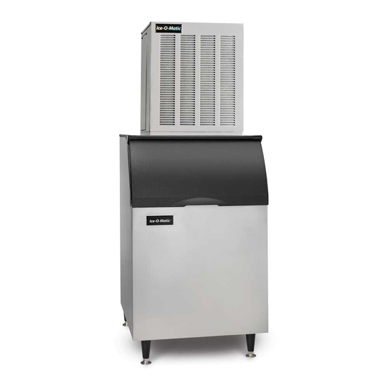
- Page 9 MFI Series Bin Application The MFI Series is designed to fit the following Ice-O-Matic Bins. ●B42, using Bin Top KBT 24 ●B25, B40 B55 using Bin Top KBT19. ●B100 using Bin Top KBT 23 (one unit) or KBT 22 (two units).
- Page 10 If the ice machine is to be mounted on a bin or dispenser other than an Ice-O-Matic, refer to the manufacturer’s instructions for machine mounting. Ice-O-Matic will not be responsible for damage or injury that results from unexpected closing of the bin door as a result of the ice machine being too far forward on the bin.
- Page 11 MFI Series For the Installer Allow 6 “Clearance for Air Circulation Allow 6 “Clearance for Air Circulation A proper installation locates the Two Units on One Bin ice machine indoors, but in a place where the heat and noise it produces are not objectionable.
-
Page 12: For The Plumber
MFI Series Water Inlet: ●Air Cooled Models: The recommended water supply is clean, cold water. Use 3/8 inch O.D. copper tubing, connect to the 3/8 inch male flare at the back of the cabinet. Install a hand valve near the machine to control the water supply. -
Page 13: For The Electrician
MFI Series Electrical Connections: Check the ice machine nameplate (located on the back panel) for the voltage requirements, and minimum circuit ampacity. The ice machine requires a solid chassis to earth ground. Connect the ice machine to its own electrical circuit so it is individually fused. Voltage variation must remain within the limitations, even under starting conditions. -
Page 14: For The Installer (Check List)
MFI Series Final Check List: 1. Is the ice machine installed indoors in a location where the air and water temperatures are _______ controlled and where they do not exceed the design limitations? _____2. Is there an electrical service disconnect within sight of the installed machine? _____3. -
Page 15: Start Up
8. Give the owner/user the service manual, instruct him/her in the operation of the unit, and make sure they know who to call for service. 9. Fill out the manufacturer’s registration and mail it to Ice-O-Matic. Page 9 Start Up... -
Page 16: Component Description
MFI Series ●Control Box: Contains the electrical controls that operate the machine. ●High Pressure Cut Out Switch: An auto-reset switch sensing the high side refrigeration pressure. It will shut the machine off if the discharge pressure exceeds 450 psig. ●Low Pressure Cut Out Switch: An auto-reset switch sensing the low side refrigeration pressure. It will disconnect power to the circuit board and shut down the machine if the low pressure falls too low. - Page 17 MFI Series ●Contactor: A definite purpose contactor connecting the compressor and the fan motor to the power supply. ●Circuit Board: Controls the operation of the ice machine using input from the sensors and pressure controls. Switches loads on and off thru relays. (Reference Photo Below) ●Potential Relay: The compressor start relay.
- Page 18 MFI Series ●Evaporator: A refrigerated vertical tube filled with water and containing a water seal and auger. ●Auger: A solid stainless steel double spiral auger, it pushes the ice crystals up to the top of the evaporator. ●Water Seal: A two part “face” seal, the top half rotating with the auger, the bottom half stationary, the sealing action being where the two “faces”...
-
Page 19: Electrical Sequence
MFI Series Electrical Sequence: There are 7 indicator lights on the control board: ●WTR-OK: (Water OK) Green. Normal=Glowing. Glow when there is water in the reservoir. ●PWR-OK: (Power OK) Green. Normal=Glowing. Glows when the power board has power and is functional. -
Page 20: Operation: Water
MFI Series Operation: Water Water enters the machine through the 3/8 inch male flare at the rear of the cabinet, goes to the water reservoir which it enters through the float valve. The water then goes out the bottom of the reservoir tank to the bottom of the evaporator. -
Page 21: Operation: Performance
MFI Series Beginning at the compressor, the refrigerant is compressed into a high temperature gas. The discharge line directs this gas to the condenser. At the condenser (air or water cooled) the gas is cooled by either air or water and then it condenses into a liquid. -
Page 22: Sanitizing And Cleaning
MFI Series It is the USER’S RESPONSIBILITY to keep the ice machine and ice storage bin in a sanitary condition. Without human intervention, sanitation will not be maintained. Ice machines also require occasional cleaning of their water systems with a specifically designed chemical. That chemical dissolves mineral build up that forms during the ice making process. -
Page 23: Bearing Maintenance
MFI Series Bearing Maintenance: The bearing in the breaker should also be checked at least two (2) times per year. Switch the machine OFF and check the bearing. 1. Remove the chute cover. 2. Unscrew the ice sweep 3. Removing the water shed and unscrewing the breaker cover. -
Page 24: Sensor Maintenance
MFI Series Bin Control Sensor: The bin control uses devices that sense light, therefore they must be kept clean enough so that they can “see”. At least twice a year, remove the bin control sensors from the base of the chute, and wipe the inside clean, as illustrated. -
Page 25: Maintenance: Air Cooled
MFI Series Clean the air cooled condenser: Air flow on this model is from front to back, so the inside of the ice machine will have to be available to clean the air cooled condenser. Use a vacuum cleaner or coil cleaner if needed. DO NOT use a wire brush. -
Page 26: Auger Maintenance
MFI Series Auger: In some areas, the water supply to the ice machine will contain a high concentration of minerals, and that will result in an evaporator and auger becoming coated with these minerals, requiring a more frequent removal than twice per year. If in doubt about the condition of the evaporator and auger, the auger can be removed so the parts can be inspected. -
Page 27: Service Diagnosis
MFI Series Symptom No ice is made nothing operates. No ice, auger motor is turning. Possible Cause •Unit off due to no power •Unit off due to master switch in OFF position •Unit off due to low water level •Unit off due to ice level sensors. - Page 28 MFI Series Symptom Unit makes ice, but very slowly Water leak. Excessive water use. Excessive ice meltage. Machine makes too much noise. Possible Cause •High discharge pressure because of a dirty condenser. •Low capacity because the auger and evaporator are coated with mineral scale.
-
Page 29: Control System Diagnostics
MFI Series The Control System consists of: ●Control Board ●Water Sensors ●Ice Sensors ●High Pressure Cut Out ●Low Pressure Cut Out If the unit is OFF, check the control board: 1. Is the Power OK light on? If not check power to the unit. If it has power, and the Power OK light is not on, check the high pressure and low pressure cut outs. -
Page 30: Removal And Replacement: Water Reservoir And Bin Controls
MFI Series Water Reservoir: 1. Disconnect electrical power supply. 2. Shut off water supply to the ice maker. 3. Remove the front panel. 4. Disconnect water inlet tube from reservoir inlet fitting. 5. To remove float valve, push in “locking tabs” as shown and pull float up. -
Page 31: Removal And Replacement: Bearing And Breaker
Replace top seal and check the O-Rings, replace if cut or torn. 8. Reverse to reassemble: Specific tools and materials are required to install properly. a. Add food grade grease such as Ice-O-Matic PN6051036-01 to the seal area before installing on the auger. -
Page 32: Removal And Replacement: Auger
MFI Series To Remove the Auger: 1. Disconnect electrical power. 2. Turn off the water to the machine. 3. Unclip the evaporator drain hose, pull it down and drain the evaporator into the bin or container. 4. Remove the top panel. -
Page 33: Removal And Replacement: Water Seal
MFI Series To Remove the Water Seal: (Assuming all steps to remove the auger have been performed) 1. The gear motor/evaporator assembly will have to be exposed. 2. Remove the four (4) hex head cap screws holding the evaporator to the gear motor assembly. -
Page 34: Removal And Replacement: Evaporator
MFI Series To Replace the Evaporator: (Assuming all steps for removal of the thrust bearing, breaker, auger and water seal have been performed). 1. Recover the refrigerant from the ice machine. 2. Unsweat the refrigerant connections: a. At the thermostatic expansion valve outlet. -
Page 35: Removal And Replacement: Gear Motor
MFI Series To Check the Gear Motor: 1. Remove wires from terminals 1 and 2 2. Use an ohmeter to check for continuity. If there is none, replace only the motor. If there is continuity but the motor will not start, check the motor’s start switch. -
Page 36: Removal And Replacement: Fan Blade And Fan Motor
MFI Series To Remove the Condenser Fan Motor Assembly: 1. Disconnect electrical power to the ice machine 2. Remove top panel and the service panels. 3. Unplug the fan motor wire leadsfrom the fan motors. 4. Remove the two (2)head bolt from the top end of the fan motor assembly. (Fig 1) 5. -
Page 37: Refrigeration System Service
MFI Series Refrigeration Service: General: This ice machine uses R404A refrigerant and polyolester oil. Do NOT use mineral oil in this refrigeration system. ●When the refrigeration system is serviced, a special liquid line drier is required. It is included with replacement compressor. -
Page 38: Wiring Diagrams
MFI Series MFI0500 Wiring Diagram Wiring Diagram MFI0500 Air, MFI0500 Water Page 32... - Page 39 MFI Series MFI0800 Wiring Diagram Wiring Diagram MFI0800 Air, MFI0806 Air, MFI0806 Water W/BK Page 33...
- Page 40 MFI Series MFI0805/1255 Wiring Diagram Wiring Diagram MFI0805, MFI1255 Air Page 34...
- Page 41 MFI Series MFI1256 Wiring Diagram Wiring Diagram MFI1256 Air Page 35...
-
Page 42: Service History
MFI Series What to Do Before Calling for Service: ●Check the water supply to the ice machine. The ice machine is designed to shut off if there is no water to it. Check the water filters if there are any.
Need help?
Do you have a question about the MFI and is the answer not in the manual?
Questions and answers