
Related Manuals for Invacare Delta II


Summary of Contents for Invacare Delta II
-
Page 1: Service Manual
® Invacare Delta II Service-Anleitung SERVICE MANUAL ® Invacare Delta II This manual includes instructions on troubleshooting & repair Version: 01.02... - Page 2 ® Invacare Delta II Service-Anleitung...
-
Page 3: Table Of Contents
Prior to Operation / After Completion of Service:..............7 Tool List..........................7 ® The Invacare Delta II ..................9 Arrangement of Modules, Components and Operator Controls ..........9 Electronic Control Components, Electrics................11 Module Composition / Variants, Accessories............... 12 3.3.1 Module Composition, Variants.................. - Page 4 ® Invacare Delta II Service-Anleitung 7.1.2 Rear Shroud, Cable Harness/Lights................24 Wheels ..........................26 7.2.1 Driving Wheels......................... 26 7.2.2 Front Wheel ........................27 7.2.3 Cover, Tube ........................28 Front Wheel Axle-tree ......................29 Batteries ..........................30 7.4.1 Checking Batteries, Battery Cables and Strip Fuse ............30 7.4.2...
-
Page 5: General Considerations
Please consult the spare part catalogue for information on ordering spare parts. Service Technician Qualification The Delta II may be serviced and repaired by qualified personnel only. Minimum requirements: Relevant training for instance as two-wheel or orthopaedic mechanic or extensive relevant experience. -
Page 6: Safety And Assembly Guidelines
The warning symbol indicates possible hazards either to the service ® technician or the Invacare Delta II. It is imperative that you observe any safety instructions marked with this symbol. The word “Danger!” indicates that failure to heed the warning may result in significant personal injury or death. -
Page 7: During Assembly / Disassembly
When re-assembling the components, ensure that the connector locking mechanisms are properly engaged. Batteries: If you need to place the Delta II on its side during service remove the batteries before doing Orientation: Any instructions involving directions such as “left” and “right” always refer to the direction of motion assuming the user is standing behind the Delta II. - Page 8 ® Invacare Delta II Service-Anleitung Set of open-jawed and ring spanners Set of Allen keys Torque wrench (standard) Socket spanner set Set of screw drivers (flat tip, cross tip, torx) Side cutter Flat nose pliers Round nose pliers Pointed pliers...
-
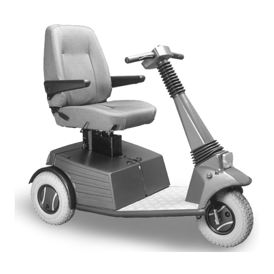
Page 9: The Invacare ® Delta Ii
® Invacare Delta II Service-Anleitung ® The Invacare Delta II Arrangement of Modules, Components and Operator Controls... - Page 10 ® Invacare Delta II Service-Anleitung...
-
Page 11: Electronic Control Components, Electrics
® Invacare Delta II Service-Anleitung Electronic Control Components, Electrics... -
Page 12: Module Composition / Variants, Accessories
Delta II Service-Anleitung Module Composition / Variants, Accessories 3.3.1 Module Composition, Variants ® The Invacare Delta II can be supplied with the following options: • Batteries (Section 6.4) 12V/50 AH (Sonnenschein) 12V/70 AH (MK Batteries) 12V/70 AH (Sonnenschein) • Throttle Control Lever (Section 6.8) Foot throttle •... - Page 13 ® Invacare Delta II Service-Anleitung Basket-mountable • Hour Meter • Spring Module, Standard, cpl. Spring module Intermediate plate Seat plate • Spring Module with Shock Absorber and Slide Rails Spring module • Self-adhesive Bags • Programming Unit Standard, for customers P &...
-
Page 14: Inspection Procedures
® Invacare Delta II Service-Anleitung Inspection Procedures Component Inspection Action Section • ⇒ Replace parts Shrouds: Rear, 7.1, 7.6.5 Check for damage Side, Seat Post • Check shroud attachment ⇒ Tighten or replace screws Shroud • ⇒ Check mounting plate Wheels: 7.11... - Page 15 ⇒ Tighten screws, if Check brake lever necessary, adjust or replace lever • ⇒ Check brake lever and Brake lever in “front” position: Delta II can be drive, adjust or replace if pushed required • ⇒ Check electronics and Brake lever in “rear”...
- Page 16 ® Invacare Delta II Service-Anleitung Ball bearing/tiller shaft adjust or replace friction shroud, friction swivel swivel joints joints • ⇒ If required replace light 7.1.2, Check function 7.10 bulbs or cables • ⇒ If required, replace cables Check cabling •...
-
Page 17: Troubleshooting
Carry out the required tests and/or repairs. Refer to and read the associated manual sections or documentation pointed out in the cross references. Root Causes Delta II does not start Push brake lever Brake lever in „rear“ to front position... - Page 18 ® Invacare Delta II Service-Anleitung Delta II bucks during driving Replace drive Drive unit Sec. 7.7 defective unit Batteries empty Charge batteries Operating manual Batteries cannot be charged Battery defective Replace battery Sec. 7.4 Charger defective Replacer charger Horn defective Sec.
-
Page 19: Fault Diagnostics With The Status Indicator Or The Penny & Giles Sp1 Programming Unit
P & G programming unit. Otherwise you may impair safe operation of the Delta II due to incorrect programming or diagnosis. You can identify the faults indicated by the SP1 Programming Unit (Penny & Giles) using the table... - Page 20 ® Invacare Delta II Service-Anleitung Possible control fault 0203 Possible control fault 0204 Error / throttle control lever 0810 Faulty cable / motor 1400 Fault / Brake 1500 Possible control fault 1501 Fault / Brake 1502 Over-voltage / Battery 1600...
-
Page 21: Fault Types And Their Possible Root Causes
WARNING: Any manipulation of the P & G Programming Unit will void the warranty. In addition, the safety of the Delta II can no longer be guaranteed which may give rise to serious liability claims against the person or organisation who caused the defects. - Page 22 Check the following voltage readings for a rocker throttle control lever or a unidirectional throttle control lever. Ensure that the throttle control lever is in 0 position and the Delta II is set to maximum speed. The nominal voltage readings should be as follows:...
-
Page 23: Repair And Replacement
® Invacare Delta II Service-Anleitung Repair and Replacement Replacing Shrouds 6.1.1 Side Shroud Disassembling the Side Shroud Turn the two turn-lock fasteners in direction of motion and lift the shroud from the fasteners. The recess (see arrow) eases lifting the shroud. -
Page 24: Invacare Delta
® Invacare Delta II Service-Anleitung Secure the side part by turning the turn-lock fasteners by 90 degrees. 6.1.2 Rear Shroud, Cable Harness/Lights Disassembling the Rear Shroud Disengage the rear light connector safety on the electronic box and pull the remove the connector. - Page 25 ® Invacare Delta II Service-Anleitung Disassembling the Cable Harness Mark the individual wires in the cable harness and take note of their positions. Pull off the rear light and direction indicator lamp cap connectors. Remove cable ties. Lift out cable harness and place next to the rear shroud as indication how the new cable routing should look like.
-
Page 26: Wheels
® Invacare Delta II Service-Anleitung Insert side parts (see above). Wheels 6.2.1 Driving Wheels WARNING: Prepare the vehicle by putting it on its side onto a support (which shouldn’t be too soft) or securely jack up the vehicle so that no load applies to the driving wheels. -
Page 27: Front Wheel
® Invacare Delta II Service-Anleitung 6.2.2 Front Wheel WARNING: Prepare the vehicle by putting it on its side onto a support (not too soft) so that no load applies to the front wheel and it can be easily accessed from both sides or, alternatively, jack up vehicle securely. -
Page 28: Cover, Tube
® Invacare Delta II Service-Anleitung 6.2.3 Cover, Tube WARNING: Prepare the vehicle by putting it on its side onto a support (not too soft) so that no load applies to the front wheel / the driving wheels and they can be easily accessed from both sides or, alternatively, jack up vehicle securely. -
Page 29: Front Wheel Axle-Tree
® Invacare Delta II Service-Anleitung Front Wheel Axle-tree WARNING: Prepare the vehicle by putting it on its side onto a support (not too soft) so that no stress applies to the front wheel and it can be easily accessed from both sides or jack up vehicle securely. -
Page 30: Batteries
® Invacare Delta II Service-Anleitung Batteries WARNING: Observe the safety guidelines (refer to section 2). Do not short-out the battery terminals; otherwise you may cause a short. Be careful when lifting the battery to avoid injury. Remove any rings and metal jewellery from hands and wrists. -
Page 31: Disassembling The Batteries
® Invacare Delta II Service-Anleitung 6.4.2 Disassembling the Batteries Remove the side shrouds (refer to section 7.1.1). Remove connector on the electronic box. Lift plastic caps from the battery terminals and remove the hexagon nuts. Remove the terminal clamps from the battery terminals. -
Page 32: Electronic Box And Components
® Invacare Delta II Service-Anleitung Electronic Box and Components WARNING: Remove Batteries. WARNING: Prepare the vehicle by putting it on its side onto a support (not too soft) so that the underbody under the electronic box can be easily accessed or, alternatively, jack up vehicle securely. -
Page 33: Seat Unit
® Invacare Delta II Service-Anleitung (charging) fuses. Remove two hexagon socket nuts at the casing rear panel and lift out fuse holder including the two spacers. Seat Unit 6.6.1 Seat WARNING: Fold back fully to the front onto the seat to prevent tipping after removing the screws. -
Page 34: Slide Rails
® Invacare Delta II Service-Anleitung 6.6.2 Slide Rails WARNING: Take care when handling slide rails, adjusting levers and springs to prevent injury. Disassembling the Slide Rail Turn over the removed seat with folded back. Remove four Allen screws. You can loosen the top screw in the slide rail through the cut-out in the rail (see picture, circle), however, this screw cannot be fully removed. -
Page 35: Seat Plate
® Invacare Delta II Service-Anleitung 6.6.4 Seat Plate Remove the seat (see 7.6.1) Take off the seat plate. -
Page 36: Seat Post
® Invacare Delta II Service-Anleitung 6.6.5 Seat Post WARNING: DANGER! Before you disassemble the seat post ensure that the seat is fully extended. If this is not the case the gas pressure spring will be pressurised. NOTE: In any case, the gas pressure spring will retain some pressure to give a lift of a few millimetres which is required for its proper function. -
Page 37: Drive
® Invacare Delta II Service-Anleitung Drive WARNING: Jack up vehicle securely. In order to be able to remove the drive you must have a ground clearance of at least 150 mm. Be aware of the drive unit weight, otherwise personal injury may occur. Once servicing has been completed, carry out a function test and test drive the vehicle. -
Page 38: Tiller, Console, Keypad
® Invacare Delta II Service-Anleitung Tiller, Console, Keypad WARNING: Upon completion of service on the throttle control lever or keypad carry out function test and test drive the vehicle. Danger of Accident! Disassembling the Tiller, Console & Keypad Throttle Control Lever Remove two Philips screws. -
Page 39: Tiller Shaft Shroud, Tiller Shaft
® Invacare Delta II Service-Anleitung Console Disassemble tiller and keypad (see above) Remove cable ties. Remove screws connecting the console to the tiller shaft (see figure) Pull console from the tiller shaft, carefully lift out connector strips. Assembling the Tiller, Console & Keypad... - Page 40 ® Invacare Delta II Service-Anleitung Disassembling the Friction Swivel Joints NOTE: Disassembly is possible without first removing the tiller shaft shroud.. Slide the lower shock absorber onto the tiller shaft shroud. Loosen the side screws & nuts of the inner or outer swivel joint somewhat (Allen screw and nut).
- Page 41 ® Invacare Delta II Service-Anleitung adjust with the tiller shaft in vertical position. Assembling the Tiller Shaft Shroud and the Tiller Shaft Screw the friction swivel joints to the tiller shaft shroud and install the shroud. Screw the friction swivel joints to the front shroud (see picture).
-
Page 42: Front Shroud, Front Wheel Fork, Lights, Horn
® Invacare Delta II Service-Anleitung 6.10 Front Shroud, Front Wheel Fork, Lights, Horn Disassembling the Front Shroud Remove console, tiller shaft shroud and tiller shaft (refer to sections 7.8 and 7.9). Unplug connector from headlight and indicator lights. Remove cable tie and pull cable harness out of the front shroud.. -
Page 43: Chassis
® Invacare Delta II Service-Anleitung Disassembling the Light Components Unplug headlight and indicator light connectors. Pull off indicator lights. Unscrew the headlights from the plate (see figure). Replacing the Bulbs Unscrew the lamp reflectors. Pull the indicator light socket from the rubber sleeve. - Page 44 ® Invacare Delta II Service-Anleitung 7.6.1, 7.6.4 and 7.6.5). Remove 4 Allen screws and unscrew gas pressure spring plate (see picture). Loosen battery straps. Remove the drive locking springs. Unscrew the drive locks.
-
Page 45: Appendix
® Invacare Delta II Service-Anleitung Appendix: Circuit Diagram... - Page 46 ® Invacare Delta II Service-Anleitung...
Need help?
Do you have a question about the Delta II and is the answer not in the manual?
Questions and answers