Table of Contents
Advertisement
Advertisement
Table of Contents

Related Manuals for Invacare Scooter


Summary of Contents for Invacare Scooter
- Page 1 Invacare® Meteor Scooter User Manual...
- Page 2 How can you get in touch with Invacare®? If you have any questions or need support, please contact your authorised Invacare® Dealer, who has the necessary know-how and equipment plus the special knowledge concerning your Invacare® product, and can offer you all-round satisfactory service. Should you wish to contact Invacare® directly, you can reach us in Europe at the following addresses and phone numbers.
- Page 3 Invacare® AS Grensesvingen 9 0603 Oslo Norge (Kundeservice): +47 - 22 57 95 10 Fax (Kundeservice): +47 - 22 57 95 01 Invacare® PORTUGAL Lda Rua Senhora de Campanhã, 105 4369-001 Porto PORTUGAL +352-225105946 Fax: +352-225105739 Invacare® n.v. Autobaan 14...
-
Page 4: Table Of Contents
Before driving for the first time...17 Taking Obstacles...18 Driving up and down gradients...19 Parking and stationary...20 4.4.1 Activating and de-activating the parking brake (option) ...20 Pushing the scooter by hand Disengaging Motors ...21 The Control Panel Control Panel layout...22 6.1.1 Seat Lifter Button ...23... - Page 5 6.1.2 Status display ...23 6.1.3 Battery charge display ...24 Driving the Scooter ...25 Diagnostics and Trouble Shooting...26 6.3.1 Diagnosing Faults ...27 Error Codes and Diagnostic Codes...28 Adjustment features Adjusting the backrest angle ...31 Moving the seat position forwards or backwards...32 Disengaging the seat to rotate it or remove it ...33...
- Page 6 10.1.1.1 Removing the rear wheel...50 10.1.1.2 Removing the front wheel (4-wheeler version)...51 10.1.1.3 Removing the front wheel (3-wheeler version)...52 10.1.1.4 Repairing punctured tyres ...53 11 Technical specifications 12 Inspections Performed...
-
Page 7: Introduction
Introduction Dear User, Thank you for purchasing an Invacare® product! We hope you will enjoy your new Scooter. This manual contains important hints and information on: Safety Operation Care and maintenance. Please familiarise yourself thoroughly before making your first trip. -
Page 8: Invacare
Important symbols in this manual WARNING: This symbol warns you of danger! Follow the instructions to avoid injury to the user or damage to the product! NOTE: This symbol indicates hints and suggestions which should help make operating the product easier and point out special functions. -
Page 9: Safety Notes
Safety Notes READ WELL BEFORE OPERATION! General Safety Notes Danger of injury if this scooter is used in any other way than the purpose described in this manual! Adhere strictly to the instructions in this user manual! Danger of injury if the scooter is driven when your ability to drive is impaired by... - Page 10 Do not exceed the maximum permissible load (see technical specifications)! Danger of injury when lifting heavy components! When maintaining, servicing or lifting any part of your scooter, take into account the weight of the individual components, especially the batteries! Be sure at all times to adopt the correct...
- Page 11 Danger of injury by moving parts! Make sure that no injury is incurred by moving parts of the scooter, like wheels or a Seat Lifter, especially when children are around! Danger of fire or breaking down due to electric devices being connected! Do not connect any electric devices to your vehicle that are not expressly certified by Invacare®...
-
Page 12: Safety Information With Regard To Care And Maintenance
Safety information with regard to care and maintenance Danger of accident and loss of guarantee if maintenance is insufficient! For reasons of safety and in order to avoid accidents which result from unnoticed wear, it is important that this electric vehicle undergoes an inspection once every year under normal operating conditions (see inspection plan contained in service instructions)! Under difficult operating conditions such as daily travel on steep slopes, or in the case of use in medical care cases with frequently changing wheelchair users, it would be expedient to... -
Page 13: Safety Information On Electromagnetic Interference
Safety Information on Electromagnetic Interference This electric vehicle was successfully tested in accordance with International standards as to its compliance with Electromagnetic Interference (EMI) Regulations. However, electromagnetic fields, such as those generated by radio and television transmitters, and cellular phones, can influence the functions of electric vehicles. -
Page 14: Safety Information On Driving And Freewheel Mode
Safety Information on Driving and Freewheel Mode Danger of injury if the vehicle tips over! Only ever negotiate gradients of up to the maximum defined in the Technical Specifications and only with the backrest in an upright position, and the seat lifter in the lowest position (if installed)! Only ever drive downhill at a maximum of 2/3rds of the top speed! Avoid abrupt braking or accelerating on gradients! - Page 15 Danger of injury if the vehicle tips over! (Continued) Never use the vehicle to transport more than one person! Do not exceed the maximum permissible load! When loading the vehicle, always distribute the weight evenly! Always try to keep the centre of gravity of the vehicle in the middle, and as close to the ground as possible! Note that the vehicle will brake or accelerate if you change the Driving Speed while it is in motion!
-
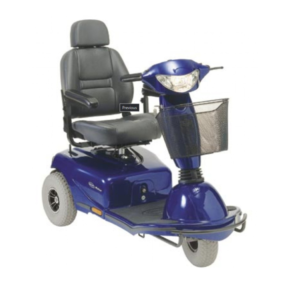
Page 16: Key Features
Key features 1) Driving lever 2) Lever for adjusting steering column inclination 3) Control panel 4) Handbrake / wheel lock 5) Keyswitch (ON/OFF) 6) Release lever for sliding seat rails (front right below seat) 7) Release lever for swivelling and removing seat (right below seat) 8) Disengaging lever... -
Page 17: Driving
Driving Before driving for the first time... Before you take your first trip, you should familiarise yourself well with the operation of the vehicle and with all operating elements. Take your time to test all functions and driving modes. NOTE: If installed, use the restraining systems (seat belts) each time you use the vehicle. -
Page 18: Taking Obstacles
Taking Obstacles Your Invacare® Meteor can climb obstacles and kerbstones up to 11 cm in height. CAUTION: Danger of Tipping Over! Never approach obstacles at an angle! Put your backrest into an upright position before climbing an obstacle! Driving up over an obstacle Approach the kerb or obstacle slowly head-on. -
Page 19: Driving Up And Down Gradients
Driving up and down gradients The Invacare® Meteor can safely climb the following inclines: 10 km/h versions: 3-wheeler (up to 175 kg load): 4-wheeler (up to 200 kg load): 12.8 km/h (8 MPH, UK) and 15 km/h versions: 3- and 4-wheeler (up to 150 kg load):... -
Page 20: Parking And Stationary
Parking and stationary When parking your vehicle or if your vehicle is stationary for a prolonged period: Switch the vehicle's power system off (key switch). Activate the parking brake (if available). 4.4.1 Activating and de-activating the parking brake (option) Activating the brake Pull brake lever (1) and hold it. -
Page 21: Pushing The Scooter By Hand
Pushing the scooter by hand The motors of the scooter are equipped with automatic brakes, preventing the scooter from rolling away out of control when the power supply is switched off. When pushing the scooter, the magnetic brakes must be disengaged. -
Page 22: The Control Panel
The Control Panel Control Panel layout Seat Lifter button (if installed) Battery charge indicator Hazard flashers Horn Right turn signal Driving speed adjustment Throttle lever Plug for external charger Reduced Speed Mode 10) Left turn signal 11) Lights... -
Page 23: Seat Lifter Button
NOTE If the Seat Lifter is not lowered entirely, then the speed of the scooter is automatically reduced to lower the risk of tipping over. This is indicated by the LED just above the "Reduced Speed Mode" button flashing. Lower the Lifter completely to restore speed to it's normal level. The LED will go out. -
Page 24: Battery Charge Display
Only red diodes lit / flashing: battery reserve = very low drive range! Charge batteries immediately! NOTE Total discharge protection: After a certain drive time on reserve battery power the electronics switches off the drive automatically and the scooter will be immobile. -
Page 25: Driving The Scooter
NOTE If the scooter does not respond after switching on, check the status display (see chapter "Status display" on page 23 and chapter "Diagnostics and Trouble Shooting" on page 26). Set the driving speed with the speed adjustment knob. -
Page 26: Diagnostics And Trouble Shooting
The electronics system provides diagnostics information to assist technicians to diagnose and correct faults within the scooter system. The existence of a fault will cause the status light to flash in bursts, separated by a pause. The nature of the fault is indicated by the number of flashes in each burst, also referred to as the Flash Code. -
Page 27: Diagnosing Faults
6.3.1 Diagnosing Faults Use the following troubleshooting guide if the scooter fails to operate. NOTE Turn the key switch on before beginning any diagnostics. If the Status Light is OFF Check that the key switch is turned ON. Check that all cables are connected correctly. -
Page 28: Error Codes And Diagnostic Codes
Drive inhibited Battery charge is empty. Recharge the batteries. If the scooter is left off for a few minutes, battery charge may recover sufficiently to allow driving for a short period of time. You should only ever do this in an... - Page 29 Drive inhibited Error Impact on Scooter The scooter has drawn too much current for too long, possibly because the motor has been over-worked, jammed or stalled. Turn the scooter power off, leave it off for a few minutes, and then turn the power back on again.
- Page 30 Number of Fault flashes Other Internal Errors Impact on Scooter Drive inhibited Contact your authorised Invacare® Dealer. Notes...
-
Page 31: Adjustment Features
Adjustment features Adjusting the backrest angle The backrest is held firm by a metal plate on both sides. Both plates have four holes which allow the backrest to be adjusted for various angles. You can do this by selecting various combinations for the holes. -
Page 32: Moving The Seat Position Forwards Or Backwards
Moving the seat position forwards or backwards The disengaging lever for adjusting the seat is located front right below the seat Pull the lever (1) to disengage the seat. Slide the seat forwards or backwards into the required position. Let go the lever again to lock the seat into its required position. -
Page 33: Disengaging The Seat To Rotate It Or Remove It
Disengaging the seat to rotate it or remove it The seat can be turned to one side to make getting in and out of the scooter easier. The seat is also easier to remove from this position. The lever for disengaging the seat is located under the seat (1) on the right. -
Page 34: Adjusting The Armrest Width
Adjusting the armrest width The hand wheels for adjusting the armrests are located under the seat (1). Turn the hand wheels to loosen the fixing for the armrest. Adjust the armrests to the required width. Retighten the handwheels... -
Page 35: Adjusting The Armrest Height
Adjusting the armrest height The hand wheels for adjusting the armrest height are located on the armrests (1). Turn the hand wheels to loosen the fixing for the armrest (1). Adjust the armrests to the required height. Retighten the handwheels... -
Page 36: Adjusting The Seat Height
Adjusting the seat height The seat height can be adjusted to the following heights (measured from chassis / floor): 46 / 64 cm 48 / 66 cm 49 / 68 cm 51 / 71 cm Requirements: 2x open-ended spanners 17 mm Removing the seat Remove the battery and motor compartment cover. -
Page 37: Adjusting The Suspension
Adjust the seat height. Reinsert the bolt and tighten. Adjusting the suspension The Meteor suspension can be individually adjusted. These adjustments should only be carried out by trained specialists. Please contact your authorised Invacare specialist dealer. -
Page 38: Electrical System
Electrical System Electronics Protection System The vehicle's electronics are equipped with an overload-protection system. If the motors are put under considerable strain for a longer period of time (for example, when driving up a steep hill) and especially when the ambient temperature is high, then the electronic system could overheat. -
Page 39: The Main Fuse
The entire electric system is protected against overload by two master fuses. The master fuses are mounted on the positive battery cables. NOTE A defective main fuse may be replaced only after checking the entire electric system. An Invacare® specialised dealer must perform the replacement. Batteries 8.2.1 What you need to know about batteries Power is supplied by two 12V gel batteries. - Page 40 The batteries cannot be overcharged with the specified charger. Please use only charging devices in Class 2. This class of chargers may be left unattended during charging. All charging devices which are supplied by Invacare® and comply with these requirements.
-
Page 41: Charging The Batteries
Danger of explosion and destruction of batteries if the wrong battery charger is used! Only ever use the battery charger supplied with your vehicle, or a charger that has been approved by Invacare®! Danger of electric shock and damage to the battery charger if it is allowed to get wet! - Page 42 (1) (maximum charge current 8A). The other is located on the front side of the battery and motor compartment (2) (maximum charge current 15A). Connecting the battery charger First connect the battery charger to the scooter. Then connect the battery charger to the mains. Disconnecting the battery charger from the scooter First disconnect the battery charger from the mains.
-
Page 43: Removing And Fitting Batteries
8.2.3 Removing and fitting batteries WARNING: Danger of injury if the batteries are not handled correctly during assembly and maintenance work! New batteries should be installed by authorised technicians! Observe the warnings on the batteries! Take into account the heavy weight of the batteries! Only ever use the battery type defined in the technical specifications! Danger of fire and burns if battery terminals are short-circuited! DO NOT short-circuit battery terminals with a tool! -
Page 44: Removing The Batteries
8.2.3.1 Removing the batteries Requirements: 2x open-ended spanners 11 mm Remove seat (see chapter "Releasing seat for turning or removal" on page "33". Remove the battery and motor compartment covers by pulling on the rear edge. Disconnect the two battery cable plug connections (1). - Page 45 Release the battery holder strap. Removing the batteries. Loosen the black cable battery clamp on the negative battery terminal with the open-ended spanner, and remove the cable. Loosen the red cable battery clamp on the positive battery terminal with the open-ended spanner, and remove the cable.
-
Page 46: How To Handle Damaged Batteries Correctly
Only ever transport damaged batteries in an appropriate acid-resistant receptacle. Wash all objects that have come into contact with acid with lots of water. Disposing of dead or damaged batteries correctly Dead or damaged batteries can be given back to your dealer or directly to Invacare®. -
Page 47: Care And Maintenance
Care and maintenance NOTE: Have your vehicle checked once a year by an authorised Invacare® dealer in order to maintain it's driving safety and roadworthiness. Cleaning the vehicle When cleaning the vehicle, pay attention to the following points: Only use a damp cloth and gentle detergent. - Page 48 Once a year you should have your vehicle inspected and serviced by your authorised dealer. A complete checklist of necessary maintenance work can be found in the Service Manual, which can be obtained from Invacare®. Maintenance Jobs Before every trip...
-
Page 49: Repair Instructions
The following are instructions on repairs that can be performed by the user. For the specifications of spare parts please see "Technical specifications" on page 55, or consult the Service Manual, available from Invacare®. In case you require assistance, please contact your Invacare® Dealer. 10.1... -
Page 50: Repairing Punctures (Pneumatic Tyres Of Type 4.00 - 5)
Problems when removing wheel? It may be necessary to use a special tool Please ask your Invacare® dealer to help you. Reassembly Reassembly takes place in reverse order. -
Page 51: Removing The Front Wheel (4-Wheeler Version)
10.1.1.2 Removing the front wheel (4-wheeler version) Requirements: Open spanner, 17 mm. Rubber hammer Jack the scooter up and place a wooden block or similar under it to support it. Remove the wheel locknut (1) with a 17 mm open-ended spanner. -
Page 52: Removing The Front Wheel (3-Wheeler Version)
10.1.1.3 Removing the front wheel (3-wheeler version) Requirements: 2x open-ended spanners 17 mm Carefully tip the scooter onto one side. Remove the wheel locknuts (1) using both open-ended spanners, then remove the wheel from the fork. Reassembly Reassembly takes place in reverse order. Make sure that the wheels are reassembled to give... -
Page 53: Repairing Punctured Tyres
10.1.1.4 Repairing punctured tyres Requirements (general) inner tube repair set or a new inner tube talcum powder open-ended spanner, 13 mm Remove valve cap. De-inflate the tyre by pressing in the centre valve pin. Remove the four nuts (1) on the rear of the wheel using the 13 mm open-ended spanner. - Page 54 Did the old inner tube get wet during the repair? If you repaired the old inner tube and reused it, and it became wet during repair, it is much easier to refit it into the wheel if you lightly powder it with talcum powder. Refit the wheel rim parts from outside into the tyre.
-
Page 55: Technical Specifications
Technical specifications Electrical system Motor (10 km/h) Motor (12.8 km/h, 8 MPH, UK) Motor (15 km/h) Batteries Main fuses (10 km/h) Main fuses (12.8 km/h, 8 MPH, UK) Main fuses (15 km/h) Weight Without batteries, without seat Without batteries With 70 Ah batteries Weight of heaviest part Maximum load (operating load) - Page 56 Dimensions Height Width Length (with bumper and anti-tip device) Seat height (measured from chassis / from floor, manually adjustable) Backrest height (without headrest) Backrest height (with headrest) Backrest angle (manually adjustable) Seat width Seat depth Armrest height Tyres Tyre pressure 3-wheeler version 4-wheeler version 123 cm*...
- Page 57 3-wheeler version Travelling performance Speed 10 km/h 12.8 km/h (8 MPH, UK) 15 km/h Safe climbing of inclines 10 km/h version up to 175 kg operating load: 12.8 km/h (8 MPH, UK) and up to 150 kg operating load: 15 km/h versions up to 175 kg operating load: Maximum obstacle height 11 cm...
- Page 58 ** Note: The scooter drive range is heavily dependent on various factors such as the battery charger status, the environmental temperature, the flatness of the route chosen, the state of the roads, the tyre pressure, the driver's weight, driving style and use of batteries for lighting, actuators etc.
-
Page 59: Inspections Performed
It is confirmed by stamp and signature that all jobs listed in the inspection schedule of the Service and Repair Instructions have been properly performed. The list of the inspection jobs to be performed can be found in the Service Manual which is available through Invacare®. Delivery Inspection...
Need help?
Do you have a question about the Scooter and is the answer not in the manual?
Questions and answers