Franke FTU 3807 I XS Instructions For Use And Installation
Hide thumbs
Also See for FTU 3807 I XS:
- Instructions for use and installation (88 pages) ,
- Handbook (16 pages) ,
- Instructions for use and installation (72 pages)

Related Manuals for Franke FTU 3807 I XS


Summary of Contents for Franke FTU 3807 I XS
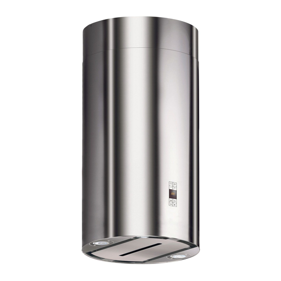
- Page 1 Istruzioni per l’uso e l’installazione Cappa Instructions for use and installation Cooker Hood Mode d’emploi et installation Hotte de Cuisine Bedienungsanleitung und Einrichtung Dunstabzugshaube FTU 3807 I XS – IN2...
-
Page 2: Table Of Contents
Instructions Manual INDEX RECOMMENDATIONS AND SUGGESTIONS ........................18 CHARACTERISTICS................................19 INSTALLATION ..................................21 USE.......................................26 MAINTENANCE..................................27... -
Page 3: Recommendations And Suggestions
RECOMMENDATIONS AND SUGGESTIONS INSTALLATION • The manufacturer will not be held liable for any damages resulting from incorrect or improper installation. • The minimum safety distance between the cooker top and the extrac- tor hood is 650 mm. • Check that the mains voltage corresponds to that indicated on the rating plate fixed to the inside of the hood. -
Page 4: Characteristics
CHARACTERISTICS Dimensions... - Page 5 Components Ref. Q.ty Product Components Hood Body, complete with: Controls, Light, Blower, 14.1 Filters 14.2 Chimney Upper Telescopic frame complete with extractor, consisting of: 7.1a Upper frame 7.1b Lower frame 7.1a Air Outlet Grill Reducer Flange ø 150-120 mm 14.1 Air Outlet Connection Extension 14.2 Air Outlet Extension...
-
Page 6: Installation
INSTALLATION Drilling the Ceiling/shelf and fixing the frame DRILLING THE CEILING/SHELF • Use a plumb line to mark the centre of the hob on the ceiling/support shelf. • Place the drilling template 21 provided on the ceiling/support shelf, making sure that the template is in the correct position by lining up the axes of the template with those of the hob. - Page 7 FIXING THE FRAME • Unfasten the two screws fastening the upper chimney stack 2.1 to the frame, and remove the chimney from the upper stack. If you wish to adjust the height of the frame, proceed as follows: • Unfasten the four safety screws located at the top in the frame separation area.
- Page 8 Ducted version air exhaust system Connection When installing the ducted version, connect the hood to the chimney using either a flexible or rigid pipe ø 150 or 120 mm, the choice of which is left to the installer. • To install a ø 120 mm air exhaust connection, insert ø...
- Page 9 Fitting the Upper Chimney and the Hood Body • Position the upper chimney stack and . x the top of it to the frame using 2 of the screws removed as above. • Open the lighting unit by pulling on the notch, disconnect it from the hood canopy by sliding out the pin.
- Page 10 ELECTRICAL CONNECTION • Connect the hood to the mains through a twopole switch having a contact gap of at least 3 mm. • Open the lighting unit by pulling on the notch. • Remove the filters one at a time by pushing them towards the back of the group and pulling down at the same time.
-
Page 11: Use
Control board Function Display Switches the extractor motor on and off at the Indicates the selected speed. latest selected speed Decreases the suction speed. Increases the suction speed. By pressing this key it is possible to activate HI appears. The spot down on the right side the intensive speed from any previously se- flashes once a second. -
Page 12: Maintenance
MAINTENANCE REMOTE CONTROL (OPTIONAL) The appliance can be controlled using a remote control powered by a 1.5 V carbon-zinc alkaline batteries of the standard LR03- AAA type. • Do not place the remote control near to heat sources. • Used batteries must be disposed of in the proper manner. Cleaning the Comfort Panels •... - Page 13 Metal grease filters Filters can be washed in the dish machine. They need to be washed when FF-sign appears on the display or in any case every 2 months, or even more frequently in case of particularly inten- sive use of the hood. Alarm reset •...
- Page 14 Charcoal filter (recycling version) • This filter cannot be washed or regenerated. It must be replaced when the EF appears on the display or at least once every 4 months. Activation of the alarm signal • In the recycling version hoods the filter saturation alarm must be activated during the instal- lation or later.
- Page 15 Umwelt und Gesundheit werden durch falsches Entsorgen gefährdet. Weitere Informationen über das Recycling dieses Produkts erhalten Sie von Ihrem Rathaus, Ihrer Müllabfuhr oder dem Geschäft, in dem Sie das Produkt gekauft haben. Franke S.p.a. Via Pignolini,2 37019 Peschiera del Garda (VR) www.franke.it...
Need help?
Do you have a question about the FTU 3807 I XS and is the answer not in the manual?
Questions and answers