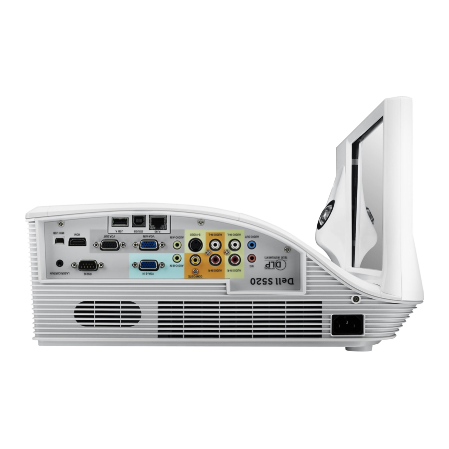
Dell S520 Quick Manual
Interactive projector screen/whiteboard ptdrv
Hide thumbs
Also See for S520:
- User manual (130 pages) ,
- Setup manual (102 pages) ,
- Replacing manual (42 pages)
Advertisement
Quick Links
Advertisement

Summary of Contents for Dell S520
- Page 1 Dell Interactive Projector S520 Screen/Whiteboard PTDRV...
-
Page 2: Important Safety Instructions
Important Safety Instructions WARNING: Failure to read, thoroughly understand, and follow all instructions can result in serious personal injury, damage to equipment, or voiding of factory warranty! It is the installer’s responsibility to make sure all components are properly assembled and installed using the instructions provided. -
Page 3: Product Dimensions
Product Dimensions 14.02 in. (356.2 mm) Side View 5.02 in. Front View (127.4 mm) 4.99 in. (126.7 mm) 78.75 in. (2000.1 mm) 80.37 in. (2041.4 mm) 41.60 in. 38.77 in. (1056.5 mm) (984.8 mm) 15.23 in. (386.8 mm) 6.6 in. (167.52 mm) 1.21 in. -
Page 4: Tools Required For Installation
Tools Required for Installation 1/8 in. (wood) 7/16” Wrench #2 Phillips Screwdriver 1/4” Washer (3) 1/2 in. (drywall) 8 mm (concrete) 6 mm (concrete – AF6 toggler) Carpenter’s Level Ruler 1/4” x 1-1/2” Lag Screw (3) Parts Included InstallationHardware #8 x 3/4” Screw (1) #8 x 1”... -
Page 5: Installation
Installation Determine desired height of image (measured from floor) Determine location of studs behind drywall. (Figure 1). Drill one pilot hole into a wall stud at location Determine desired center of image area (Figure 1). marked in Step 3 (Figure 1). Measure 4-1/16”... - Page 6 Installation (continued) Center of NOTE: The (3) 1/4” x 1-1/2” bolts and (3) washers required in Screen Steps 6-8 are NOT INCLUDED with the screen/whiteboard packaging. Previously Drilled Hole Install (1) 1/4” x 1-1/2” bolt and (1) washer through middle of bracket into previously drilled hole, leaving 1/2”...
- Page 7 Concrete wall or no studs: (3) supplied #8-10 wall anchors and (3) supplied #8 x 1” screws. 11. Install projector mount. Refer to the S520 Dual Stud Wall Mount (MSP-DCCUST2) manual. Do not install the (2) plastic covers for mount (Figure 4).
- Page 8 Installation (continued) 13. Mount screen onto wall bracket by hooking into the back groove of the screen frame (Figure 6). NOTE: The bumpers on the back side of the screen/whiteboard are used to maintain planarity when pressure is applied to the projection surface during usage.
- Page 9 Concrete wall or no studs: (1) supplied #8-10 wall anchor and (1) #8 x 1” screw. 19. Secure IR sensor bar (packaged with the S520 Projector) to screen by sliding it onto the metal bracket. Insert safety screw through IR sensor bar into bracket (Figure 11).
- Page 10 NOTE: Two cable clips are shipped with the screen/ Figure 12 whiteboard. For some installations, only one cable clip may be needed. 22. Install projector mount covers and projector (Figure 14). Refer to the S520 Dual Stud Wall Mount (MSP-DCCUST1) manual. Figure 13 Figure 14...
- Page 11 Recommended Screen/Whiteboard Markers Cleaning This Dell S520 Screen/Whiteboard is a dual-purpose projection The supplied cleaning cloth can be used to clean marks on the screen and whiteboard. The surface of the screen/whiteboard Dell S520 Screen/Whiteboard surface made by everyday dry can be used with dry erase markers from a wide variety of erase marker usage.
- Page 12 Installation Video For further guidance and helpful information about installing an S520 Dual Stud Wall Mount and S520 Screen/Whiteboard, please reference the installation video: http://downloads.chiefmfg.com/MANUALS-I/Dell Interactive Solution.mp4 • • Go to http://downloads.chiefmfg.com/MANUALS- Go to http://downloads.chiefmfg.com/MANUALS- • Go to http://downloads.chiefmfg.com/MANUALS- •...


Need help?
Do you have a question about the S520 and is the answer not in the manual?
Questions and answers