
Related Manuals for Yardworks 060-3808-8

Summary of Contents for Yardworks 060-3808-8
- Page 1 ELECTRIC LAWN EDGER 060-3808-8 Owner's Manual TOLL-FREE HELPLINE: 1 866 523-5218 WARNING WARNING Read all safety rules and instructions carefully before operating this tool.
-
Page 2: Table Of Contents
CONTENTS Contents ............................2 Specifications ..........................2 Important Safety Instructions ....................3-5 Specific Safety Rules .......................... 6 Symbols ............................ 7-8 Electrical ..........................9-10 Know your edger ........................11-12 Assembly ..........................12-14 Operation ..........................15-20 Maintenance ..........................21-23 Troubleshooting ........................Warranty ............................. Parts List ..........................26-27 Specifications Electric lawn edger Input ....................120 V, AC only, 60 Hz, 12 Amps... -
Page 3: Important Safety Instructions
IMPORTANT SAFETY INSTRUCTIONS WARNING: Read and understand all instructions. Failure to follow all instructions listed below may result in electric shock, fire and/or serious personal injury. READ ALL INSTRUCTIONS • Read the operator’s manual carefully. Be thoroughly familiar with the controls and the proper use of the equipment. - Page 4 IMPORTANT SAFETY INSTRUCTIONS • Service on the product must be performed by qualified repair personnel only. Service or maintenance performed by unqualified personnel could result in injury to the user or damage to the product. • Use only identical replacement parts when servicing the product. Use of unauthorized parts may create a risk of serious injury to the user, or damage to the product.
-
Page 5: Important Safety Instructions
IMPORTANT SAFETY INSTRUCTIONS • Maintain Edger with Care – Keep sharp cutting edge clean for best performance and to reduce the risk of injury. Follow instruction for lubricating and changing accessories. Inspect edger cord periodically, and if damaged, have it repaired by an authorized service facility. Inspect extension cords periodically and replace if damaged. -
Page 6: Specific Safety Rules
SPECIFIC SAFETY RULES • Be sure all guards are properly and securely attached. • Replace dull or worn blade; do not attempt to sharpen. • Do not attempt to sharpen blade. Failure to heed this warning could result in excessive vibration causing serious personal injury or property damage. -
Page 7: Symbols
SYMBOLS Some of the following symbols may be used on this product. Please study them and learn their meaning. Proper inter- pretation of these symbols will allow you to operate the product better and safer. SYMBOL NAME DESIGNATION/EXPLANATION Volts Voltage Amperes Current Frequency (cycles per second) -
Page 8: Symbols
To avoid serious personal injury, do not attempt to use this product until you read thoroughly and understand completely the operator’s manual. If you do not understand the warnings and instructions in the operator’s manual, do not use this product. Call YARDWORKS customer service for assistance. -
Page 9: Electrical
ELECTRICAL WARNING: TO AVOID ELECTRICALHAZARDS, FIRE HAZARDS, OR DAMAGE TO THE TOOL, USE PROPER CIRCUITPROTECTION. YOUR EDGER IS WIRED ATTHE FACTORYFOR 120 V OPERATION. CONNECTTO A120 V, 15 ACIRCUITAND USE A15 ATIME DELAYED FUSE OR CIRCUITBREAKER. TO AVOID SHOCK OR FIRE WHEN THE POWER CORD IS WORN, CUT, OR DAMAGED IN ANYWAY, REPLACE IT IMMEDIATELY. - Page 10 ELECTRICAL WARNING: THIS EDGER IS FOR OUTDOOR USE ONLY. DO NOT EXPOSE TO RAIN OR USE IN DAMP LOCATIONS. GUIDELINES FOR USING EXTENSION CORDS USE THE PROPER EXTENSION CORD. Make sure your extension cord is in good condition. When using an extension cord, be sure to use one of heavy enough gauge to carry the current your product will draw.
-
Page 11: Know Your Edger
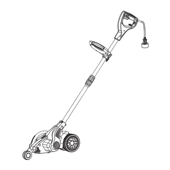
KNOW YOUR EDGER LOCK-OFF BUTTON REAR HANDLE SWITCH TRIGGER ADJUSTABLE FRONT HANDLE CORD RETAINER LEVER HANDLE ADJUSTING POLE KNOB EDGER GUARD POWERHEAD POLE WHEELS BLADE SPRING ASSIST FRONT WHEEL Fig. 2... -
Page 12: Assembly
KNOW YOUR EDGER KNOW YOUR EDGER (See Figure 2.) The safe use of this product requires an understanding of the information on the tool and in this operator’s manual as well as a knowledge of the project you are attempting. Before use of this product, familiarize yourself with all operating features and safety rules. - Page 13 ASSEMBLY CONNECTING THE POLES (See Figure 3.) Before using the edger, a one-time assembly is required. When removed from the box, the two poles are connected by an electrical cord as shown below. 1. Remove packaging material from cord and discard. 2.
-
Page 14: Assembly
ASSEMBLY ASSEMBLING THE FRONT WHEEL (See Figure 4.) Before using the edger, a one-time assembly is required. When removed from the box, the front wheel is as shown above (A). 1. Screw off the adjusting knob from the hole (1). 2. -
Page 15: Operation
OPERATION WARNING: Do not allow familiarity with this product to make you careless. Remember that a careless fraction of a second is sufficient to inflict serious injury. WARNING: Always wear safety goggles or safety glasses with side shields when operating power tools. Failure to do so could result in objects being thrown into your eyes, resulting in possible serious injury. - Page 16 OPERATION STARTING AND STOPPING (See Figure 5.) To start the motor: Plug the edger into an AC power outlet. Press and hold the Lock-off button and squeeze the switch trigger. The edger will stay ON as long as the trigger switch is squeezed. To stop the motor: ...
- Page 17 OPERATION POSITION AUXILIARY HANDLE (See Figure 6.) Turn the LEVER 90°. Adjust the auxiliary handle to the desired position. Press the LEVER to the LOCK position. DOWN LEVER UNLOCK LOCK Fig. 6...
- Page 18 OPERATION ADJUSTING TELESCOPING POLE (See Figure 7.) Disconnect the edger from the power supply. Rotate the collar counterclockwise to loosen. Push poles towards each other to shorten the pole or pull away from each other to lengthen the pole. ...
- Page 19 OPERATION ADJUSTING DEPTH OF CUT (See Figures 8-9.) The front wheel can be adjusted to allow a deeper or shallower cut, and to increasethe life of the blade. Change the edging depth from the shipping position to your desired depth by: ...
-
Page 20: Operation
OPERATION OPERATING TIPS NOTE: The edger requires a lot of power and should not be operated simultaneouslywith other tools or utilities on the same household circuit. Set initial cut depth at 1” and set edge guide to the down posotion. ... -
Page 21: Maintenance
MAINTENANCE WARNING: When servicing, use only identical replacement parts. Use of any other parts may create a hazard or cause product damage. WARNING: Always wear safety goggles or safety glasses with side shields during power tool operation or when blowing dust. If operation is dusty, also wear a dust mask. WARNING: Before inspecting, cleaning or servicing the unit, stop the motor, wait for all moving parts to stop, and disconnect from power supply. - Page 22 MAINTENANCE REPLACING THE BLADE (See Figures 10 - 11.) Replace blades that are damaged or worn. To increase blade life span, keep initial cutting depth at minimum and increase depth setting only as blade wears. Stop the motor and unplug the edger. ...
- Page 23 MAINTENANCE STORING THE EDGER Be sure the tool is unplugged. Remove and clean any debris from the outside of the edger and inside of the guard before storage. If necessary, the edger may be stored by hanging on a hook by the handle. ...
-
Page 24: Troubleshooting
TROUBLESHOOTING PROBLEM POSSIBLE CAUSE SOLUTION Motor fails to start when 1. Power cord is not plugged in or 1. Plug in the power cord. switch trigger is depressed. connection is loose. 2. Household circuit breaker is tripped. 2. Check circuit breaker. -
Page 25: Warranty
WARRANTY For TWO YEARS from the date of purchase within Canada, YARDWORKS ® CANADA will, at its option, repair or replace for the original purchaser, free or charge, any part or parts found to be defective in material or workmanship. -
Page 26: Parts List
PARTS LIST... - Page 27 PARTS LIST Item No. Part No. Description Blade nut 3221037 Blade washer 3330418A 7 1/2” Blade 33301261 Screw 3220351 Blade guard 34103263 Seal ring 34908261 Motor 36101263-1 Nut M8 32208261 Washer 3220898 Nut M6 32907152 Front wheel height adjustment bracket 33303263 3”...
Need help?
Do you have a question about the 060-3808-8 and is the answer not in the manual?
Questions and answers