Table of Contents
Advertisement
Quick Links
WARNING:
If the information in these instructions is not followed exactly, a fire or explosion may result causing
property damage, personal injury or loss of life.
-
Do not store or use gasoline or other flammable vapors and liquids in the vicinity of this or any other appliance.
WHAT TO DO IF YOU SMELL GAS
• Do not try to light any appliance.
• Do not touch any electrical switch; do not use any phone in your building.
• Immediately call gas supplier from a neighbor's phone. Follow the gas supplier's instructions.
• If you cannot reach your gas supplier, call the fire department.
-
Installation and service must be performed by a qualified installer, service agency or the gas supplier.
This appliance may be installed in an
aftermarket permanently located,
manufactured home (USA only) or mobile
home, where not prohibited by local codes.
This appliance is only for use with the
type(s) of gas indicated on the rating
plate. A conversion kit is supplied with
the appliance.
INSTALLER:
Leave this manual with the appliance.
CONSUMER:
Retain this manual for future reference.
© Copyright 2012, T.I.
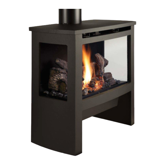
Cypress GSR
Owner's Manual
$10.00
100-01329
• Direct Vent Freestanding Stove
• Natural Gas or Propane
AS 4553-2008
IAPMO-R&T OCEANA
Dragon Wholesaling Pty. Ltd.
Unit 2, 16 Lexington Drive
4121109
Listed by
GMK10053
Bella Vista NSW 2153
Australia
Advertisement
Table of Contents

Subscribe to Our Youtube Channel
Related Manuals for Lopi Cypress GSR


Summary of Contents for Lopi Cypress GSR
- Page 1 This appliance is only for use with the type(s) of gas indicated on the rating plate. A conversion kit is supplied with the appliance. Cypress GSR Dragon Wholesaling Pty. Ltd. Unit 2, 16 Lexington Drive Owner’s Manual Bella Vista NSW 2153 INSTALLER: Leave this manual with the appliance.
-
Page 2: Introduction
Do not mail your Bill of Sale to us. Model: Cypress GSR We suggest that you attach your Bill of Serial Number: Sale to this page so that you will have all the information you need in one place... -
Page 3: Table Of Contents
Table of Contents Table of Contents For installation instructions, consult the Introduction ............2 instructions included with the log, stone, or Important Information ........2 driftwood............. 25 Table of Contents ..........3 Before You Begin ........... 26 ... -
Page 4: If You Smell Gas
Safety Precautions • IF YOU SMELL GAS: * Do not light any appliance * Extinguish any open flame * Do not touch any electrical switch or plug or unplug anything * Open windows and vacate building * Call gas supplier from neighbor's house, if not reached, call fire department •... - Page 5 Safety Precautions • Do not place clothing or • Light the heater using the other flammable items on or built-in igniter. Do not use near the heater. Because matches or any other this heater can be controlled external device to light your by a thermostat there is a heater.
-
Page 6: Features
Specifications Features: Installation Options: Works During Power Outages (battery backup system) Freestanding Stove Blower and Remote Control Included Horizontal or Vertical Vent Standing or Intermittent (GreenSmart) Pilot Residential or Mobile Home High Efficiency Straight or Corner Placement Convenient Operating Controls Bedroom Approved Variable-Rate Heat Output Accent Light... -
Page 7: Installation Warnings
Installation (for qualified installers only) Installation Warnings: Failure to follow all of the requirements may result in property damage, bodily injury, or even death. This heater must be installed by a qualified installer who has gone through a training program for the installation of direct vent gas appliances. -
Page 8: Packing List
Installation (for qualified installers only) Packing List Additional Items Required • • Remote Control Vent (see “Venting Requirements” for details) • • Propane Conversion Kit Gas Line Equipment (shutoff valve, pipe, etc.) • • Touch-Up Paint Approved Travis Media (Logs 94500561, •... -
Page 9: Stove Clearances
Installation (for qualified installers only) Stove Clearances Top Vent Straight Installations Top Vent Corner Installations With this clearance the top vent is centered 6-7/8" (175mm) from the back wall, 25-1/8" (638mm) from With this clearance, the vent is the side wall. centered 16-1/2"... -
Page 10: Heater Placement Requirements
Installation (for qualified installers only) Heater Placement Requirements • Heater must be installed on a level surface capable of supporting the heater and vent. • Due to the high temperature, the heater should be located out of traffic and away from furniture and draperies. -
Page 11: Gas Line Installation
Installation (for qualified installers only) Gas Line Installation The gas line must be installed in accordance with all local codes. The heater and gas control valve must be disconnected from the gas supply piping during any pressure testing of that system at test pressures in excess of 1/2 psig (3.45 kPA). For pressures under 1/2 psig (3.45 kPA), isolate the gas supply piping by closing the manual shutoff valve. -
Page 12: Vent Requirements
Installation (for qualified installers only) Vent Requirements • The gas appliance and vent system must be vented directly to the outside of the building, and never be attached to a chimney serving a separate solid fuel or gas-burning appliance. Each direct vent gas appliance must use it's own separate vent system. -
Page 13: Approved Vent Configurations
Installation (for qualified installers only) Approved Vent Configurations Exhaust Restrictor Position • An exhaust restrictor is built into the appliance to control the flow rate of exhaust gases. This ensures proper flames for the wide variety of vent configurations. Depending upon the vent configuration, you may be required to adjust the restrictor position. -
Page 14: Closing The Diffuser (Stock Position Is Open)
Installation (for qualified installers only) Closing the Diffuser (stock position is open) -- (for top vent configurations only) IMPORTANT NOTE: The diffuser can be easily closed with no vent in place. Consult the vent configuration charts to determine diffuser position. If the diffuser needs to be in the closed position, adjust the diffuser prior to installing vent. -
Page 15: Exhaust Restrictor Extender (For Rear Vent Configurations Only)
Installation (for qualified installers only) Exhaust Restrictor Extender (for rear vent configurations only) • Follow the directions below to install the exhaust restrictor extender. Remove these two screws on the exhaust restrictor. Use the screws to attach the extender to the exhaust restrictor. -
Page 16: Rear Vent Configuration With Horizontal Termination
Installation (for qualified installers only) Rear Vent Configuration with Horizontal Termination • Use the rear vent conversion from Travis Industries (SKU 94400998). • Use 8” Diameter Vent • Horizontal sections require a ¼” (6mm) rise every 12” (305mm) of travel. •... -
Page 17: Rear Vent Configuration With Vertical Termination
Installation (for qualified installers only) Rear Vent Configuration with Vertical Termination • Use the rear vent conversion from Travis Industries (SKU 94400998). • Use 8” Diameter Vent • Horizontal sections require a ¼” (6mm) rise every 12” (305mm) of 31' max (9.3m) 31' max (9.3m) travel. -
Page 18: Top Vent Configuration With Vertical Termination
Installation (for qualified installers only) Top Vent Configuration with Vertical Termination • Use 6-5/8” Diameter Vent • Horizontal sections require a ¼” (6mm) rise every 12” (305mm) of travel. • A maximum of four (4) 45° or 90° elbows may be used. Of these elbows, only one (1) may be a horizontal elbow (see illustration). -
Page 19: Top Vent Configuration With Horizontal Termination
Installation (for qualified installers only) Top Vent Configuration with Horizontal Termination • Use 6-5/8” Diameter Vent • Horizontal sections require a ¼” (6mm) rise every 12” (305mm) of travel. • A maximum of four (4) 45° or 90° elbows may be used. Of these elbows, only one (1) may be a horizontal elbow (see illustration). -
Page 20: Vent Termination Requirements (See Illustration Below)
Installation (for qualified installers only) Vent Termination Requirements (see illustration below) Venting terminals shall not be recessed into a wall or siding. Minimum 9" (229mm) clearance from any door or window Roof Minimum 12" (305mm) above any grade, veranda, porch, deck or balcony Surface Minimum 12"... -
Page 21: Steps For Finalizing The Installation
Installation (for qualified installers only) Steps for Finalizing the Installation Remove the glass (see page 23). NOTE: If using propane (LP) convert the appliance prior to installing the logs, driftwood, or stone set. We recommend you purge the gas line at this time (with the glass removed). This allows gas to be detected once it enters the firebox, ensuring gas does not build up. -
Page 22: Air Shutter Adjustment
Installation (for qualified installers only) Check the air shutter following the directions below. Air Shutter Adjustment Let the heater burn for fifteen minutes (make sure the media and glass are in place). The flames should be yellow with no sooting. Adjust the air shutter, if necessary, to achieve the correct looking flame. Correct Not Enough Air Too Much Air... -
Page 23: Face And Glass Removal
Finalizing the Installation (for qualified installers only) Face and Glass Removal Make sure the gas control valve is “OFF” and the heater is cool prior to conducting service. Open the two latches holding the Phillips Screwdriver glass frame in place - follow the directions shown below Remove the two screws securing the stove top. - Page 24 Finalizing the Installation (for qualified installers only) Glass Frame Removal and Installation (continued) The latch can come loose from glass frame anchor. This occurs when it is turned 1/4 turn when it is disengaged. Follow the directions below to re-install the latch if it becomes loose. Hold the latch at an angle and insert it into the slot on the glass frame anchor.
-
Page 25: Media Installation (Log, Stone, Or Driftwood)25
Finalizing the Installation (for qualified installers only) Media Installation (Log, Stone, or Driftwood) The logs are fragile, especially after being exposed to heat. • Make sure the gas control valve is “OFF” and the heater is cool prior to conducting service. •... -
Page 26: Before You Begin
Operation Before You Begin Warning: Read this entire manual before you use your new stove (especially the section "Safety Precautions" on pages 4 & 5). Failure to follow the instructions may result in property damage, bodily injury, or even death. Warning: Do not operate appliance with the glass front removed, cracked or broken. -
Page 27: Starting The Stove For The First Time
Operation Starting the Stove for the First Time • Burn the heater at a high setting with the blower off for an extended period (up to 48 hours). This will cure the painted surfaces. Fumes from the paint curing and oil burning off the steel will occur. This is normal. -
Page 28: Accent Light
Operation Accent Light This stove has a built-in accent light HIGH that may be turned on and off and dimmed to your preference. Turn the knob to achieve the desired light output. ACCENT LIGHT Adjusting the Standard Blower Speed The blower helps transfer heat from the heater into the room. It will not turn on until the heater is up to temperature (approximately 15 minutes after starting). -
Page 29: Remote Operation
Operation Remote Operation Once the receiver is switched to “REMOTE” the transmitter operates the fireplace. Once you understand how the transmitter works, you will be able to operate your fireplace quickly and easily. Changing the Display to Celcius (C) With the remote off, press the thermostat and mode button simultaneously. This will toggle between Fahrenheit and Celcius. -
Page 30: Manual On-Off / Smart Thermostat / Standard Thermostat
Operation Manual On-Off / Smart Thermostat / Standard Thermostat Use the thermostat button to cycle through the three thermostat settings (see Figure 5). Look here for the Press the thermostat button to cycle through the thermostat settings. thermostat setting. SMART Figure 5 MANUAL ON/OFF –... -
Page 31: Mode Controls (Flame, Comfort Control)
Operation Mode Controls (Flame, Comfort Control) Use the mode button to cycle through the two mode controls (see Figure 9 below). Press the mode button to cycle through the mode settings. Flame Look here for Comfort Height Control mode controls. Figure 9 Flame Height Flame height may be controlled using the up and down buttons when in Flame Height Mode (see Figure... -
Page 32: Normal Operating Sounds
Operation Normal Operating Sounds Extinction Pops It is not unusual, especially on Propane The appliance may creak with change of (LP) appliances, to experience a "pop" temperature -- THIS IS NORMAL. when the burner is shut off. Blower Pilot Assembly This heater has an optional blower to push The pilot flame will make a clicking heated air into the room. -
Page 33: Low Battery Indicator
Operation Low Battery Indicator Transmitter Batteries The transmitter has a battery-level indicator. When it indicates low battery voltage (see Figure 12 below), install three new AAA alkaline batteries into the transmitter (see “Battery Installation” on page 34). Low Battery Indicator Figure 12 Receiver Batteries The receiver will “beep”... -
Page 34: Maintaining Your Stove's Appearance
Maintenance (for authorized service personnel only) DO NOT MODIFY THIS APPLIANCE Maintaining Your Stove's Appearance Painted Surfaces • Painted surfaces should be cleaned with a duster. If scratches occur, lightly sand the area with fine sandpaper. Clean the area and, with the stove cool, apply one or two thin coats of stove paint to the area (mask the area to avoid overspray). -
Page 35: Accent Light Replacement
Maintenance (for authorized service personnel only) Accent Light Replacement An accent light is included in your stove to provide additional lighting. To replace the bulb, follow the directions below: • Disconnect stove from power. Shut off gas to the stove. Make sure the stove is cool before proceeding (15 minutes). -
Page 36: Yearly Service Procedure
Maintenance (for authorized service personnel only) Yearly Service Procedure • Failure to inspect and maintain the stove may lead to improper combustion and a potentially dangerous situation. We recommend the following procedures be done by a qualified technician. Turn the pilot flame to continuous. It should touch approximately 3/8" of the top of the flame sensor. If it does not, contact your dealer for service. -
Page 37: Troubleshooting Table
Maintenance (for authorized service personnel only) Troubleshooting Table Problem: Possible Cause: Don't Call for Service Until You: The ON/OFF switch is turned to "OFF" Turn the ON/OFF switch to "ON" Main Burners Will Not The remote control is not working correctly See the remote control instructions Start The thermostat is disconnected or set too low... -
Page 38: Wiring Diagram
Maintenance (for authorized service personnel only) Wiring Diagram Caution: Label all wires prior to disconnection when servicing controls. Wiring errors can cause improper and dangerous operation. Verify proper operation after servicing. Pilot Spark Rod Comfort Control Sensor Valve PILOT DIGITAL SENSOR FIREPLACE BURNER... -
Page 39: Safety Label
Safety Label Safety Label The safety (listing) label is attached under the stove. A copy is shown below. © Travis Industries 4121109 100-01329.docx... -
Page 40: Lp Conversion Instructions
Optional Equipment (for qualified installers only) LP Conversion Instructions WARNING This conversion kit shall be installed by a qualified service agency in accordance with the manufacturer’s instructions and all applicable codes and requirements of the authority having jurisdiction. If the information in these instructions are not followed exactly, a fire, explosion or production of carbon monoxide may result causing property damage, personal injury or loss of life. - Page 41 Optional Equipment (for qualified installers only) 3. Grasp the burner with both hands and lift it straight up and out of the firebox. Discard the rear air deflector. 4. Discard the manifold cover (see below). © Travis Industries 4121109 100-01329.docx...
- Page 42 Optional Equipment (for qualified installers only) 5. Install the LP (propane) orifices. Rear Burner Orifice Front Burner Orifice Thread Sealant 15/16" 24mm 1/2" Wrench Orifice ID Natural Gas LP (Propane) ORIFICE SIZE (ID) Front Burner Orifice #49 DMS #57 DMS Rear Burner Orifice #43 DMS #53 DMS...
- Page 43 Optional Equipment (for qualified installers only) 6. Install the LP (propane) manifold cover included in owner’s pack (see illustration below). 7. Install the LP pilot orifice following the directions below. (a) Use a 7/16” open-end wrench to remove the pilot hood. (b) Remove and discard the Natural Gas (NG) orifice.
- Page 44 Optional Equipment (for qualified installers only) 9. Use the included torx wrench to remove the stock stepper motor (it may be discarded). The stepper motor (adjustable regulator) has an installation sheet included with it – make sure to follow all of the directions.
-
Page 45: Warranty
Limited 7 Year Warranty Register your Dragon Wholesaling Limited 7 Year Warranty online at lopi.com.au or complete the enclosed Warranty card and mail it within ten (10) days of the appliance purchase date to: Dragon Wholesaling Pty. Ltd. Unit 2, 16 Lexington Drive Bella Vista NSW 2153 Australia. Dragon Wholesaling warrants this gas appliance (appliance is defined as the equipment manufactured by Travis Industries, Inc.) to be defect-free in material and workmanship to the original purchaser... -
Page 46: Index
Index Index Accent Light Replacement ....... 35 Normal Operating Sounds ....... 32 Additional Items Required ........8 Power Outages ..........33 Adjusting the Standard Blower Speed ..... 28 Rear Vent Configuration with Horizontal Approved Vent Configurations ......13 Termination ..........16 Battery Replacement ........
Need help?
Do you have a question about the Cypress GSR and is the answer not in the manual?
Questions and answers