Table of Contents

Subscribe to Our Youtube Channel
Related Manuals for AMX Metreau Entry Communicator with Display MET-ECOM-D


Summary of Contents for AMX Metreau Entry Communicator with Display MET-ECOM-D
-
Page 1: Metreau Entry Communicators
Operation/Reference Guide Metreau Entry Communicators ™ MET-ECOM Metreau Entry Communicator MET-ECOM-D Metreau Entry Communicator with Display L a s t R e v i s e d : 1 2 / 0 4 / 2 0 0 8 Voice and V i de o Commu nication Sy stems... - Page 2 AMX is not responsible for products returned without a valid RMA number. AMX is not liable for any damages caused by its products or for the failure of its products to perform. This includes any lost profits, lost savings, incidental damages, or consequential damages.
-
Page 3: Table Of Contents
Table of Contents Metreau Entry Communicators ...1 Overview ... 1 Front Components ... 2 Rear Components... 3 Product Specifications - MET-ECOM ... 3 Product Specifications - MET-ECOM-D ... 5 Positioning the Camera ...7 Overview ... 7 Camera Viewing Angle Adjustment ... 7 Wiring and Connections ...9 Overview ... - Page 4 Table of Contents Installing the Metreau Entry Communicator... 27 Using Zero Configuration ...29 Overview ... 29 Bonjour (Zero-Configuration) Client... 29 Connecting In a Network With a DHCP Server ... 29 Connecting In a Network Without a DHCP Server... 30 Using the Configuration Manager ...33 Overview ...
- Page 5 Programming ...51 Overview ... 51 SEND_COMMANDs ... 51 Touch Panel Intercom Commands ... 51 RTP, RTCP Video and Audio Streaming Commands ... 53 Face Plate LED Commands... 55 Camera Commands ... 56 LCD Commands... 58 I/O Commands ... 60 System Commands ... 60 Upgrading Firmware...
- Page 6 Table of Contents Setup page... 76 Someone At The Door page ... 77 Creating Popup Pages ... 78 Door Answer Call popup page ... 78 Doorbell Adjustments popup page ... 78 Intercom Answer Call popup page ... 79 More Time popup page ... 80 Metreau Entry Communicators...
-
Page 7: Metreau Entry Communicators
The Metreau Entry Communicators (FIG. 1) can be placed at entry points of homes, condos and hotels to provide audio/video communications with anyone at a door or gate - all over IP. Any AMX Modero intercom-enabled touch panel can interface with the Entry Communicator and allow residents to open doors, gates and more. -
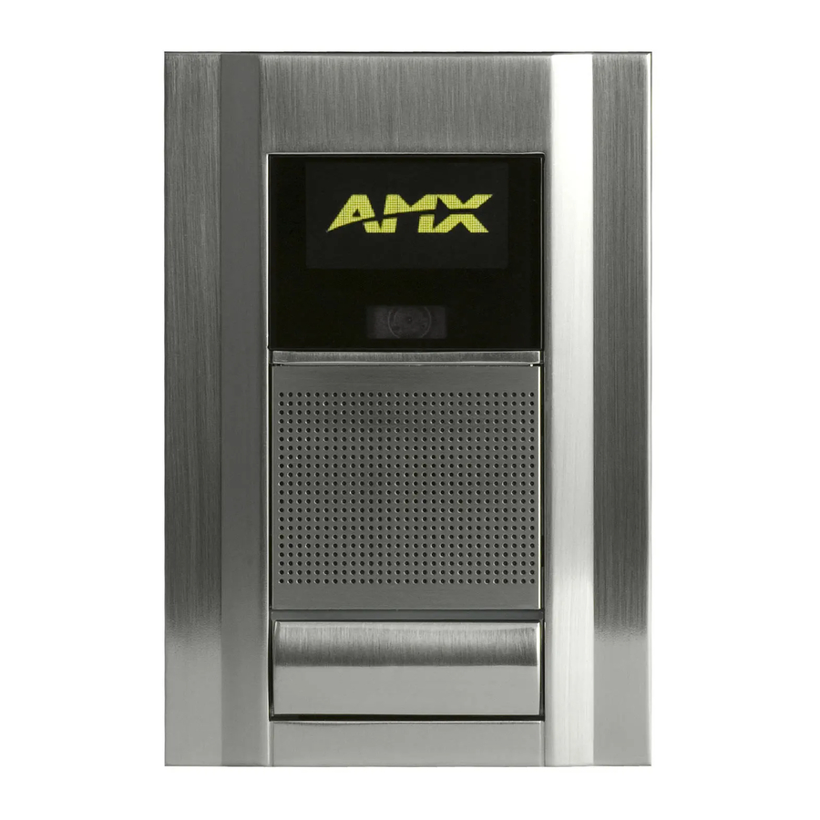
Page 8: Front Components
Metreau Entry Communicators Front Components The front components of the Metreau Entry Communicators are indicated in FIG. 2: OLED display (MET-ECOM-D only) Video Camera Speaker Dual Color LED Status Bar Pushbutton (Doorbell) Microphone FIG. 2 Metreau Entry Communicators - Front Components Metreau Entry Communicators... -
Page 9: Rear Components
Rear Components The rear components of the Metreau Entry Communicators are indicated in FIG. 3: Camera Viewing Angle Adjustment ID/Reset pushbutton STATUS (green LED) Ethernet Connection 2 Multi-Purpose I/Os (5V) 2 Low Voltage Relays (1A Contact) FIG. 3 Metreau Entry Communicators - Rear Components Product Specifications - MET-ECOM MET-ECOM Specifications Power:... - Page 10 Dimensions (HWD): Weight: Operating Environment: Mounting: Colors Available: Included Accessories: Other AMX Equipment: Certifications: • -40 dB sensitivity, built-in echo cancellation (telephone quality) • Full duplex communication • VoIP Telephony • Camera Viewing Angle Adjustment • Ethernet Port - 10/100 Ethernet with PoE. LEDs show communication...
-
Page 11: Product Specifications - Met-Ecom-D
Product Specifications - MET-ECOM-D MET-ECOM-D Specifications Power: Front Panel Components: OLED Display: Integrated Color Video Camera: • QVGA 320x240 Speaker: Microphone: Rear Panel Components: Dimensions (HWD): Weight: Metreau Entry Communicators • PoE powered – no local Power Supply needed • IEEE 802.3af Compliant •... - Page 12 MET-ECOM-D Specifications (Cont.) Operating Environment: Mounting: Colors Available: Included Accessories: Other AMX Equipment: Certifications: 32° to 104° F (0° to 40° C) The MET-ECOM-D is installed in several ways: • 4 screws for hard surface mounting • 2 expansion clips for pressure mounting •...
-
Page 13: Positioning The Camera
Positioning the Camera Overview The camera on the Metreau Entry Communicators provides a symmetrical 42° viewing angle, and by default the camera is centered. The Metreau Entry Communicators feature a Camera Viewing Angle Adjustment slider on the rear panel of the unit that allows you to adjust the viewing angle horizontally from -15°... - Page 14 Positioning the Camera Camera Viewing Angle Adjustment slider FIG. 5 MET-COM-D Camera: Left and Right Viewing Range Top view when camera is centered at 0° 42° (default) Camera Top view when camera is facing left at 15° Camera Top view when camera is facing right at 15° Camera Metreau Entry Communicators...
-
Page 15: Wiring And Connections
Using the Configuration Manager section of the Metreau Entry Communicators Operation/Reference Guide (available online at www.amx.com). Additionally, consider the location of your installation. When possible, avoid facing the device in what would be considered high traffic areas. -
Page 16: Ethernet 10/100 Base-T Rj-45 Wiring Configuration
Wiring and Connections Ethernet 10/100 Base-T RJ-45 Wiring Configuration The table below describes the pinouts, signals, and pairing for the Ethernet 10/100 Base-T connector and cable. The Ethernet cable connection is illustrated in FIG. 7. Ethernet Pinouts and Signals Signals TX + TX - RX +... -
Page 17: Input/Output (I/O) Port: Connections And Wiring
Input/Output (I/O) Port: Connections and Wiring The I/O port responds to either switch closures, voltage level (high/low) changes, or it can be used for logic-level outputs. A contact closure between the GND and an I/O port is detected as a Push. When used for voltage inputs, the I/O port detects a low signal (0 - 1.5 VDC) as a Push, and a high signal (3.5 - 5 VDC) as a Release (this IO port uses 5V logic but can handle up to 12V without harm). -
Page 18: Ferrite Installation (Required)
Wiring and Connections Ferrite Installation (Required) Metreau Entry Communicators comes with a Cat5 Suppression Ferrite that must be clipped around the Ethernet cable, inside the wall box (no tools required). 1. Release the latch to open the plastic enclosure. FIG. 8 Installing the CAT5 Suppression Ferrite When positioning the Ferrite clip inside the wall box, place the bottom of the clip flat against the back inside surface of the wall box, to allow sufficient room for the Metreau Entry Communicator unit... -
Page 19: System Diagram
NXD-1000Vi FIG. 10 Metreau Entry Communicators - System Diagram System Diagram - Intercom The following system diagram (FIG. 11) illustrates an AMX system using Metreau Entry Communicators with both wired and wireless touch panels: FIG. 11 Intercom System Diagram Metreau Entry Communicators... - Page 20 Wiring and Connections Metreau Entry Communicators...
-
Page 21: Mounting And Installation
Mounting and Installation Mounting and Installation MET-ECOM / MET-ECOM-D Installation Overview This section addresses the physical mounting of the MET-ECOM and MET-ECOM-D Metreau Entry Communicators. To avoid any damage to the electronic component, installation must be performed in an ESD safe environment. Also note that the Metreau Entry Communicator and wall box must have an earth-ground. -
Page 22: Mounting Specifications
Mounting and Installation Mounting Specifications The following illustrations (FIG. 13, FIG. 14 and FIG. 15) provide mounting specifications for the Metreau Entry Communicators conduit box (FG. Reference these measurements when planning and installing the device. Front View FIG. 13 Mounting Specifications (front view) Metreau Entry Communicators... -
Page 23: Side Views
Side Views FIG. 14 Mounting Specifications (side views) Top View FIG. 15 Mounting Specifications (top view) Metreau Entry Communicators Mounting and Installation... -
Page 24: Typical Installation (Without Expansion Clips)
Mounting and Installation Typical Installation (Without Expansion Clips) FIG. 16 provides specifications for mounting the wall box without the use of expansion clips. FIG. 16 Typical Installation (Without Expansion Clips) Be sure to install the Cat5 Suppression Ferrite (provided) before mounting the Metreau Entry Communicator unit into the wall box. - Page 25 Rough-in installation tabs Earth ground point FIG. 17 Metreau Entry Communicators wall box The device and wall box must have an Earth ground. 5. Install the (provided) Ferrite clip onto the Ethernet cable (see FIG. 8 on page 12). 6. Connect the Ethernet cable in the back of the Metreau Entry Communicator. 7.
-
Page 26: Installing The Wall Box Without The Use Of Tabs
Mounting and Installation Installing the Wall Box Without the Use of Tabs Be sure to install the Cat5 Suppression Ferrite (provided) before mounting the Metreau Entry Communicator unit into the wall box. Refer to the Ferrite Installation (Required) section on page 12 for details. A brick and mortar installation environment is a great example where no tabs are required. -
Page 27: Wall Surface Installation (Using Expansion Clips)
Wall Surface Installation (Using Expansion Clips) Expansion clips are mounted through the 2 holes located along the rim of the wall box (see FIG. 18). As the screw is tightened, the clip bends toward the insertion hole and into the wall. This bending creates a "grip"... - Page 28 5. Insert the wall box and expansion clips into the cutout until the rim of the wall box is flush against the wall. Replacement drywall clip sets must be ordered from AMX. 6. Tighten the 2 drywall clip sets (screws and clips) until the wall box is flush against the wall (FIG.
-
Page 29: Installing Into A Flat Surface Using Mounting Screws
8. Install the (provided) Ferrite clip onto the Ethernet cable (see FIG. 8 on page 12). 9. Connect the Ethernet cable in the back of the Metreau Entry Communicator. 10. Insert and fasten the Metreau Entry Communicator into the wall box. Installing Into a Flat Surface Using Mounting Screws Mounting screws (#4 flathead, not included) are secured through two sets of circular holes located at the left and right sides of the wall box. -
Page 30: Removing The Device From The Wall
Mounting and Installation 6. Place the lug of the ground wire on the device and the Earth ground wire around the provided screw and connect them both to the point shown in FIG. 17. The device and wall box must have an Earth ground. 7. -
Page 31: Using The Optional Surface Mount Box
Using the Optional Surface Mount Box The CB-MET-ECOMS (-S/-B) Surface Mount Box Kit for Metreau Entry Communicators is available for situations where it is undesirable or impossible to install the conduit box into the mounting surface. It is available in two colors: CB-MET-ECOMS-S - paintable Silver (FG039-14-S) CB-MET-ECOMS-B - Black (FG039-14-B) The Surface Mounting Box (FIG. -
Page 32: Surface Mount Box Specifications
Mounting and Installation Surface Mount Box Specifications FIG. 22 provides mounting specifications for the CB-MET-ECOMS: SIDE REAR FRONT FIG. 22 Surface Mounting Box Specifications - Top and Side Views Metreau Entry Communicators... -
Page 33: Ferrite Installation (Required)
Ferrite Installation (Required) The CB-MET-ECOMS comes with a Cat5 Suppression Ferrite that must be clipped around the Ethernet cable, inside the back box (no tools required). FIG. 23 Installing the CAT5 Suppression Ferrite 1. Release the latch to open the plastic enclosure. 2. - Page 34 Mounting and Installation 1. Run all cables through the Conduit Routing Hole on the rear panel of the Surface Mounting Box. The Conduit Routing Hole is intended to accept conduit of up to 0.500" (1.27 cm) in diameter (see FIG. 22). 2.
-
Page 35: Using Zero Configuration
Using Zero Configuration Overview Metreau Entry Communicators with firmware versions of v1.00.018 (MET-ECOM) and v1.00.020 (MET-ECOM-D) or higher support using "zero-configuration" client software to quickly install multiple devices on the network. Bonjour (Zero-Configuration) Client You can use a zero-configuration client to determine the IP address of the Metreau Entry Communicators. There are many zero-configuration clients available. -
Page 36: Connecting In A Network Without A Dhcp Server
To establish a network connection from a PC to the MET-ECOM device: 1. Direct connect a PC and MET-ECOM device with the AMX PS-POE-AF single-port PoE Injector. Alternatively, connect the PC and MET-ECOM to an Ethernet switch equipped with PoE. - Page 37 Manually set the PC's IP address to 169.254.1.1 and subnet mask to 255.255.0.0. FIG. 27 Internet Properties (TCP/IP) Properties dialog 4. Launch Internet Explorer and select the Bonjour Plug-in. 5. Double-click the MET-ECOM (Metreau-218001XXXnnnnnnn) in the Bonjour Plug-in pane and login and configure the device as needed (see Using the Configuration Manager section on page 33).
- Page 38 Using Zero Configuration Metreau Entry Communicators...
-
Page 39: Using The Configuration Manager
Using the Configuration Manager Overview Metreau Entry Communicators have a built-in web console (FIG. 28) that allows you to easily make various configuration settings via a web browser on any PC that has access to the device. The web console consists of a series of web pages that separate device configuration options by category. Collectively, the pages in the web console are referred to as the Configuration Manager. -
Page 40: Command Buttons
Using the Configuration Manager Command Buttons The Configuration Manager is divided into four primary sections, indicated by four command buttons across the top of the main page (FIG. 29): FIG. 29 Configuration Manager Command Buttons Summary: The Summary of Device page is the page that is displayed when the Configuration Manager is accessed. -
Page 41: Summary Of
Summary of <Device> Settings Page The Summary of Device Settings page (FIG. 31) is the initial view when the Configuration Manager is accessed. FIG. 31 Summary of Device Settings Page Naturally, this page can be accessed at any time via the Summary command button at the top of the web console.Settings Page -
Page 42: Checking The Firmware Version
Using the Configuration Manager Summary of Device Settings Page (Cont.) IP Settings Host IP Address Subnet Mask Gateway MAC Address NetLinx Settings Status System Number Device Number Master IP Master Port Friendly Name System Resources File System Checking the Firmware Version The firmware version is listed on the Summary of Device Settings page, in the Device Information section at the top of the page. -
Page 43: Configuration Page
Configuration Page Click the Configuration command button to access the Configuration page (FIG. 32). This page contains three tabs: IP Settings (initial view): Use the options in this tab to specify Network IP settings (see below). NetLinx Settings: Use the options in this tab specify the ICSP connection to the NetLinx master (see the Configuration Page - NetLinx Settings Tab section on page 39). -
Page 44: Setting The Ip Address
Using the Configuration Manager Configuration Page - Network IP Settings Tab IP Address Host IP Address Subnet Mask Gateway DNS Address Domain Suffix Primary DNS Secondary DNS Zero Configuration Networking ZCN On/Off Setting the IP Address 1. In the Configuration page, select the IP Settings tab. 2. -
Page 45: Configuration Page - Netlinx Settings Tab
Configuration Page - NetLinx Settings Tab Select the NetLinx Settings tab of the Configuration page to access the NetLinx Settings tab (FIG. 33). Use the options in this tab to view and edit the ICSP connection to the NetLinx master. FIG. -
Page 46: Configuration Page - User Settings Tab
Using the Configuration Manager Setting the Host Name requires DNS implementation on the IP network. 5. If you have enabled password security on your master, you need to set the username and password within the fields provided. 6. Click Accept. 7. -
Page 47: Device Utilities Page
Device Utilities Page Click the Utilities command button to access the Device Utilities page (FIG. 35). The options on this page allow you to upload, change, and display images on the MET-ECOM-D. FIG. 35 Device Utilities Page Device Utilities Page Utility Meta Information Location Description... -
Page 48: Image File Requirements
Using the Configuration Manager Device Utilities Page (Cont.) File Upload Browse Submit Images Location New Folder Image Selection Field Image File Requirements In order for images to be displayed on the MET-ECOM-D, the following image file requirements apply: BMP image type 1-bit (monochrome) 128 x 64 pixels Creating Display Images... - Page 49 2. Save the file as a ".BMP" image (FIG. 37). FIG. 37 Same image - saved as a BMP file 3. Reduce the BMP image to 128 x 64 pixels. At this point there are options - you can either crop or reduce the original image to size. In many cases, a combination of cropping and resizing may be best, depending on the size and nature of the image.
-
Page 50: Creating Dynamic Images
Use the Resource Manager feature of the TPDesign4 application to create dynamic images for use with the MET-ECOM-D. If you do not already have TPD4 installed, download and install the latest version from www.amx.com. TPDesign4 - Resource Manager The Dynamic Images tab of TPD4’s Resource Manager dialog (FIG. 40) allows you to manage images that exist on an HTTP server or FTP server, external to the panel. -
Page 51: Creating A New Dynamic Image
Creating a New Dynamic Image 1. In TPDesign4, select Panel > Resource Manager to access the Resource Manager dialog, and open the Dynamic Images tab (FIG. 40). 2. Click the New button at the top of the dialog (see FIG. 40) to invoke the Create Dynamic Image dialog (FIG. -
Page 52: Uploading A Display Image To The Device
Using the Configuration Manager Create Dynamic Image dialog (Cont.) • Refresh Rate: • Refresh only at Panel Startup: 4. Click OK. When images of any (supported) file type except PNG are imported into a project, the files are automatically converted to JPGs. For this reason, if you import (or paste) a file that has the same name as a previously imported file (even if it has a different extension), TPDesign4 automatically adds the "copy of"... -
Page 53: Audio/Video Page
Audio/Video Page Audio/Video Page - Audio Settings Tab Click on the Audio tab of the Audio/Video Page to access the Audio Settings tab (FIG. 42). Use the options in this tab to view/edit audio-specific settings. FIG. 42 Audio/Video Page - Audio Settings tab Audio/Video Page - Audio Settings Tab Audio Codec G.711 Codec... -
Page 54: Audio/Video Page - Video Settings Tab
Using the Configuration Manager Audio/Video Page - Video Settings Tab Click the Video tab in the Audio/Video Page to access the Video Settings page (FIG. 43). Use the options in this tab to view/edit video-specific settings. FIG. 43 Audio/Video Page - Video Settings tab Audio/Video Page - Video Settings Tab Video Codec Codec... -
Page 55: Setting Device Video
Audio/Video Page - Video Settings Tab (Cont.) Green Blue Flicker Correction Wired Frame Rate Wireless Frame Rate Contrast Saturation Gamma Setting Device Video 1. In the Audio/Video page, select the Video tab. 2. Click the radio button to select the Video Port type. 3. -
Page 56: Setting The Display Settings On The Device
Using the Configuration Manager Audio/Video Page - Display Settings Tab Contrast Intensity Displaying Setting the Display Settings On The Device 1. In the menu on the top of the Configuration Manager, select Audio/Video. 2. Select the tab Display. 3. Use the sliders to change the Contrast level. 4. -
Page 57: Programming
Programming Overview There are a select number of SEND_COMMANDs recognized by the Metreau Entry Communicators. SEND_COMMANDs Below is a list of SEND_COMMANDs supported by the Metreau Entry Communicators from NetLinx masters. To use these commands, establish a Telnet session from the PC to the NetLinx master. Additionally, you could use NetLinx Studio 2.4 or the master’s web page to send the commands. - Page 58 Programming Touch Panel Intercom Commands (Cont.) STREAM-SET (Cont.) STREAM-GET Retrieves a description of the stream parameter being used by the current stream. STREAM-PLAY This command notifies the Metreau Entry Communicator to start streaming by enabling the micro- phone, speaker and video source and then, transmitting packets and playing received packets.
-
Page 59: Rtp, Rtcp Video And Audio Streaming Commands
Touch Panel Intercom Commands (Cont.) ^VER? Metreau Entry Communicator version number. RTP, RTCP Video and Audio Streaming Commands Metreau Entry Communicators support the following RTP, RTCP Video and Audio Streaming SEND_COMMANDs on port 1. RTP, RTCP Video and Audio Streaming Commands GET VIDEO Retrieves the configuration of the video system. - Page 60 Programming RTP, RTCP Video and Audio Streaming Commands (Cont.) SET AUDIO Sets the current configuration of the audio system. Configuration includes codec, sam- pling rate, and bit rate. Sample rate is at 8khz. GET GAIN Retrieves the current gain setting on the microphone input.
-
Page 61: Face Plate Led Commands
Face Plate LED Commands Metreau Entry Communicators support the following LED face plate SEND_COMMANDs on port 1. Face Plate LED Commands SET LED-LEVEL Adjusts the brightness of the LED. To turn the LED ON or OFF. GET LED-LEVEL Retrieves the brightness of the LED. -
Page 62: Camera Commands
Programming Camera Commands Unlike AMX touch panels, Metreau Entry Communicators return String responses instead of Command responses. The Metreau Entry Communicators Camera (MET-ECOM-D only) supports the following camera SEND_COMMANDs on port 1. Camera Commands SET CAM-WBAL Sets the white balance control setting for the camera. - Page 63 Camera Commands (Cont.) SET CAM-CST Sets the display contrast level for the camera. GET CAM-CST Retrieves the contrast level for the camera. SET CAM-SAT Sets the display saturation for the camera. GET CAM-SAT Retrieves the saturation level for the camera. SET CAM-FLICK Sets the flicker mode setting for the camera.
-
Page 64: Lcd Commands
Example: SEND_COMMAND MET1,"'GET CAM-FLICK’" Returns: CAM-FLICK = 50 The Camera flicker setting is at 50hz mode. Syntax: SEND_COMMAND <DEV>,"'SET DISP-BANNER /mnt/amx/usr/upload/ <filename>'" Variable: • filename = Name of image file on the system to be displayed on the LCD. Example: SEND_COMMAND MET1,"'SET DISP-BANNER /mnt/amx/usr/upload/... - Page 65 LCD Commands (Cont.) SET DISP-BRT Sets the brightness level to a percentage. The LCD display sup- ports quad (25%), half (50%) and full (100%) brightness. GET DISP-BRT Retrieves the Bright- ness level for the LCD display. SET DISP-CST Sets the display con- trast.
-
Page 66: I/O Commands
Programming I/O Commands The I/O port supports the following SEND_COMMANDs on port 2. There are two channels on port 2: Channel 1 and Channel 2; I/O Commands GET INPUT Gets the input channels active state. An active state can be high (logic high) or low (logic low or contact closure). - Page 67 System Commands (Cont.) SET DOOR-DESC Set the door description text. GET DOOR-DESC Returns the door's description text. Metreau Entry Communicators Syntax: SEND_COMMAND <DEV>,"'SET DOOR-DESC <desc_num>, <desc_txt>'" Variables: • Desc_num= 1 or 2 • Desc_txt = max 20 character string Example: SEND_COMMAND STORM,"'SET DOOR-DESC 1, front door'"...
-
Page 68: Upgrading Firmware
NetLinx Master instruction manual to use an address. Note the IP Address and Gateway information. 2. Launch NetLinx Studio 2.4 (default location is Start > Programs > AMX Control Disc > NetLinx Studio > NetLinx Studio 2.4). -
Page 69: Verifying And Upgrading The Device Firmware Via An Ip
Workspace window. The default device value is 10001. 4. If the device firmware version is not the latest available; locate and download the latest firmware file from the www.amx.com > Tech Center > Downloadable Files > Firmware Files section of the website. - Page 70 Programming FIG. 46 Send to NetLinx Device dialog 6. Select the device’s firmware file from the Files section (FIG. 46). 7. Enter the Device value associated with the device and the System number associated with the Master (listed in the OnLine Tree tab of the Workspace window). The Port field is greyed-out. 8.
-
Page 71: Using The Netlinx Module
Incorporating an Intercom Panel Into Your NetLinx System Download the module for the intercom panel from www.amx.com, and include it in your NetLinx project file. For searching purposes, the module manufacturer is AMX and the model is Intercom. -
Page 72: Setting The Intercom Session Timeout
Using the NetLinx Module Setting the Intercom Session Timeout When only 30 seconds are left in your call, the panel provides a popup to extend the call (FIG. 48). Session time-outs are not applicable for calls with Metreau Entry Communicators. 1. -
Page 73: Door Setup
Using the NetLinx Module Door Setup The Door Setup page (FIG. 49) is accessed through the Intercom Setup page. The options on the Door Setup page allow you to disable/enable all doorbells, and configure the Door Chime for each Metreau Entry Communicator doorbell in the system. -
Page 74: Door Chime Setup
Using the NetLinx Module Door Chime Setup The Door Chime Setup page (FIG. 50) is accessed through the Door Setup page. The options on the Door Chime Setup page allow you to associate a particular Chime sound with each doorbell in the system. -
Page 75: Advanced Setup
Advanced Setup The Intercom Advanced Setup page (FIG. 51) is accessed through the Intercom Setup page. The options on the Intercom Advanced Setup page allow you to set the panel intercom to be monitored, to monitor other intercom panels, and to name the panel. It is important to name the intercom panel; the name is displayed in other panels’... -
Page 76: Allowing A Panel To Monitor
Using the NetLinx Module Allowing a Panel To Monitor 1. Select the Setup button on your intercom page. 2. On the intercom setup page, press Advanced Setup. This launches the password numeric keypad. 3. Enter the password and press Done. The default password is Password 4 of the panel’s firmware Password Setup. -
Page 77: Answering An Incoming Doorbell Call
Answering an Incoming Doorbell Call The provided intercom pages include a doorbell answering popup window (FIG. 54): FIG. 54 Answer Doorbell The popup page indicates the name of the doorbell calling and provides several options: Answer - Pressing this button opens the intercom session with the doorbell. View - Press to initiate one-way communication with the doorbell. -
Page 78: Ending A Doorbell Call
Creating Intercom Pages The easiest method of creating your own intercom pages is to start with the pages provided by AMX in the module. You can change the aesthetics of the pages as long as the channel, address, level and links remain untouched. -
Page 79: Door Chime Setup Page
Door Chime Setup page Door Chime Setup Name Description Chime 1 The name of the Chime 1 sound. Chime 2 The name of the Chime 2 sound. Chime 3 The name of the Chime 3 sound. Chime 4 The name of the Chime 4 sound. Chime 5 The name of the Chime 5 sound. -
Page 80: Intercom Demo Page
Using the NetLinx Module Intercom Demo page The module for duplex intercom capable panels includes user pages. While you can create your own intercom directory page (see the Creating Intercom Pages section on page 72), it is possible to use the panel with the page shown in FIG. - Page 81 Sample Intercom Page (Cont.) No. Name Panel Directory Room Name The name of a panel in the Panel Directory Room Name The name of a panel in the Panel Directory Room Name The name of a panel in the Panel Directory Room Name The name of a panel in the Call Panel Call Panel Call Panel...
-
Page 82: Setup Page
Using the NetLinx Module Sample Intercom Page (Cont.) No. Name Monitor Panel Intercom Microphone Level Intercom Sound Level Call Status Button Navigate Up Navigate Down Intercom Setup Page Setup page Setup Name Description Auto-Answer OFF Toggle the panel’s auto-answer feature off and on. Session Timeout A display of the current session timeout. -
Page 83: Someone At The Door Page
Someone At The Door page Someone At The Door Name Description StormVideo Displays video from the incoming doorbell call. Door Microphone Mutes the microphone on the incoming doorbell. 1:371 Level - Mute Door Microphone Lowers the microphone level on the incoming Level - Down doorbell. -
Page 84: Creating Popup Pages
Using the NetLinx Module Someone At The Door (Cont.) Name Description Panel Speaker Displays the current speaker level on the panel. 1:0 Level - Bargraph Creating Popup Pages Door Answer Call popup page Door Answer Call Popup Name Description Answer Opens the intercom session with the doorbell. -
Page 85: Intercom Answer Call Popup Page
Doorbell Adjustments Popup (Cont.) Name Description Panel Mutes the microphone on the panel. Microphone Level Mute Panel Lowers the microphone level on the panel. Microphone Level Down Panel Raises the microphone level on the panel. Microphone Level Up Panel Displays the current microphone level on the panel. Microphone Level Bargraph... -
Page 86: More Time Popup Page
Using the NetLinx Module More Time popup page More Time Popup Name Confirm More Time Description Select to extend intercom session beyond timeout. Channel Address Port:Code Port:Code 1:20 Metreau Entry Communicators... - Page 87 Programming Metreau Entry Communicators...
- Page 88 It’s Your World - Take Control™ 3000 RESEARCH DRIVE, RICHARDSON, TX 75082 USA • 800.222.0193 • 469.624.8000 • 469-624-7153 fax • 800.932.6993 technical support • www.amx.com...
Need help?
Do you have a question about the Metreau Entry Communicator with Display MET-ECOM-D and is the answer not in the manual?
Questions and answers