AMX MET-ECOM Instruction Manual
Metreau entry communicators
Hide thumbs
Also See for MET-ECOM:
- Dimensional drawing (3 pages) ,
- Installation manual (2 pages) ,
- Operation/reference manual (88 pages)

Related Manuals for AMX MET-ECOM


Summary of Contents for AMX MET-ECOM
- Page 1 IN STR U CT IO N MAN U AL M E T REA U ™ E N T R Y C O M M U N I C ATO RS ME T- ECOM METRE AU EN TR Y COMMUNICATOR ME T- ECOM-D METREAU ENTRY COMMUNICATOR WITH DISPLAY...
-
Page 2: Important Safety Instructions
COPYRIGHT NOTICE AMX© 2016, all rights reserved. No part of this publication may be reproduced, stored in a retrieval system, or transmitted, in any form or by any means, electronic, mechanical, photocopying, recording, or otherwise, without the prior written permission of AMX. Copyright protection claimed... -
Page 3: Table Of Contents
Using the Optional Surface Mount Box ................17 Included in the Kit ..........................17 Surface Mount Box Specifications ......................18 Ferrite Installation (Required) ......................19 Installing the Metreau Entry Communicator (MET-ECOM and MET-ECOM-D) ........19 Installing the MET-ECOM-DNS-B ......................20 Wiring and Connections ..................21 Overview ......................... 21 Rear Panel Connectors.................... - Page 4 Using the Configuration Manager ..............27 Overview ......................... 27 Command Buttons ..........................27 Accessing the Configuration Manager ....................28 Summary of <Device> Settings Page................29 Checking the Firmware Version......................30 Determining the IP settings of the Metreau Entry Communicator............30 Rebooting the Device..........................30 Configuration Page......................
- Page 5 ^MOD? ....................................45 ^VER?..................................... 45 Face Plate LED Commands........................46 SET LED-LEVEL ..................................46 GET AUDIO ..................................... 46 SET AUDIO ..................................... 46 GET GAIN ....................................46 SET GAIN ....................................46 GET VOLUME ..................................46 SET VOLUME ..................................46 Camera Commands ..........................47 SET CAM-WBAL..................................
- Page 6 Panel Intercom Configuration..................58 Intercom Setup............................. 58 Setting the Intercom Session Timeout....................58 Setting Intercom Auto Answer ......................59 Door Setup ............................59 Disabling All Doorbells .......................... 59 Door Chime Setup ..........................59 Assigning a Chime to a Doorbell......................59 Advanced Setup............................
-
Page 7: Metreau Entry Communicators
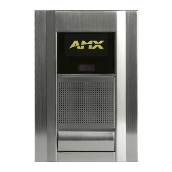
The Metreau Entry Communicators (FIG. 1) can be placed at entry points of homes, condos and hotels to provide audio/video communications with anyone at a door or gate - all over IP. Any AMX Modero intercom-enabled touch panel can interface with the Entry Communicator and allow residents to open doors, gates and more. -
Page 8: Front Components
Metreau Entry Communicators Front Components The front components of the Metreau Entry Communicators are indicated in FIG. 2: OLED display (MET-ECOM-D only) Video Camera Speaker Dual Color LED Status Bar Pushbutton (Doorbell) Microphone Metreau Entry Communicators - Front Components FIG. 2 Rear Components The rear components of the Metreau Entry Communicators are indicated in FIG. -
Page 9: Product Specifications - Metreau Entry Communicators
2 independent external relay devices. Dimensions (HWD): MET-ECOM and MET-ECOM-D: 5.364” x 3.594” x 1.559” (13.62 cm x 9.13 cm x 3.96 cm) MET-ECOM-DNS-B: 6.500” x 4.185” x 1.493” (16.510 cm x 10.629 cm x 3.792 cm) Note: Refer to the Mounting Specif ications section on page 16 for mounting dimensions. -
Page 10: Screensaver (Met-Ecom-D And Met-Ecom-Dns-B Only)
Screensaver (MET-ECOM-D and MET-ECOM-DNS-B Only) To prevent uneven wear of the LEDs in the display, the OLED screen on the front panel of the MET-ECOM-D and MET-ECOM-DNS-B will inverse (white appears black, and vice versa) the image currently on the screen. This is engaged automatically for one second every 15 minutes of operation. -
Page 11: Met-Ecom/D Mounting And Installation
MET-ECOM / MET-ECOM-D Installation Overview This section addresses the physical mounting of the MET-ECOM and MET-ECOM-D Metreau Entry Communicators. To avoid any damage to the electronic component, installation must be performed in an ESD safe environment. Also note that the Metreau Entry Communicator Rough-In Box must have an earth-ground. -
Page 12: Mounting Specifications
MET-ECOM/D Mounting and Installation Mounting Specif ications The following illustrations (FIG. 5, FIG. 6 and FIG. 7) provide mounting specifications for the (optional) Metreau Entry Communicators Rough-In Box (FG039-12). Reference these measurements when planning and installing the device. Front View Metreau Entry Communicators Rough-In Box - Mounting Specifications (front view) FIG. -
Page 13: Top View
MET-ECOM and MET-ECOM-D Typical Installation (without Expansion Clips) FIG. 8 provides specifications for mounting the Rough-In Box without the use of expansion clips. MET-ECOM and MET-ECOM-D - Typical Installation (Without Expansion Clips) FIG. 8 NOTE: Be sure to install the Cat5 Suppression Ferrite (provided) before mounting the Metreau Entry Communicator unit into the Rough-In Box. -
Page 14: Installing The Rough-In Box Without The Use Of Tabs
MET-ECOM/D Mounting and Installation Expansion clip installation tabs Rough-in Keyhole Ethernet installation tabs cable access Earth ground point Metreau Entry Communicators Rough-In Box FIG. 9 Place the lug of the ground wire on the device and the Earth ground wire around the provided screw and connect them both to the point shown in FIG. - Page 15 Insert the Rough-In Box and expansion clips into the cutout until the rim of the Rough-In Box is flush against the wall. NOTE: Replacement drywall clip sets must be ordered from AMX. Tighten the 2 drywall clip sets (screws and clips) until the Rough-In Box is flush against the wall (FIG. 11).
-
Page 16: Installing Onto A Flat Surface Using Mounting Screws
MET-ECOM/D Mounting and Installation NOTE: Do not over-torque the screw; doing so can cause the unit to not function properly Place the lug of the ground wire on the device and the Earth ground wire around the provided screw and connect them both to the point shown in FIG. -
Page 17: Removing The Device From The Wall
MET-ECOM/D Mounting and Installation Removing the Device from the Wall The installation housing for the Metreau Entry Communicators are made to such exacting specifications it will always be a snug fit. Should you ever need to remove the Metreau Entry Communicator from the wall, follow these steps: Place a flathead screwdriver between the tab of the Rough-In Box and the notch of the Metreau Entry Communicator and pop the two apart. -
Page 18: Surface Mount Box Specifications
MET-ECOM/D Mounting and Installation Surface Mount Box Specif ications FIG. 14 provides mounting specifications for the CB-MET-ECOMS: SIDE REAR FRONT Surface Mounting Box Specifications FIG. 14 Metreau Entry Communicators Instruction Manual... -
Page 19: Ferrite Installation (Required)
Metreau Entry Communicator unit. Installing the Metreau Entry Communicator (MET-ECOM and MET-ECOM-D) The Metreau Entry Communicator clips onto the front of the Surface Mount Box via the four mounting tabs (two on each side), and the mounting clip at the bottom center of the box (FIG. -
Page 20: Installing The Met-Ecom-Dns-B
MET-ECOM/D Mounting and Installation Installing the MET-ECOM-DNS-B To install the MET-ECOM-DNS-B in to the Rough-In Box: Insert the Metreau unit into the Rough-In Box at an angle, sliding the bottom in first (FIG. 17). Slide unit in until this Tab... -
Page 21: Wiring And Connections
If used with a non PoE-capable Ethernet switch (such as the NXA-ENET24), then an optional PS-POE-AF Power-over- Ethernet (PoE) power supply is required to provide power to the MET-ECOM. If the MET-ECOM is used with a PoE-capable Ethernet switch (such as the NXA-ENET24PoE), then no PoE Injectors are required. -
Page 22: Input/Output (I/O) Port: Connections And Wiring
Wiring and Connections Input/Output (I/O) Port: Connections and Wiring The I/O port responds to either switch closures, voltage level (high/low) changes, or it can be used for logic-level outputs. A contact closure between the GND and an I/O port is detected as a Push. When used for voltage inputs, the I/O port detects a low signal (0 - 1.5 VDC) as a Push, and a high signal (3.5 - 5 VDC) as a ... -
Page 23: System Diagram
FIG. 20 System Diagram FIG. 21 provides a basic NetLinx system diagram using Metreau Entry Communicators: NetLinx Master MVP-8400i MVP-5200i NXA-ENET24PoE NXA-WAP250G PS-POE-AF NXD-1000Vi NXD-700Vi MET-ECOM-D MET-ECOM Metreau Entry Communicators - System Diagram FIG. 21 Metreau Entry Communicators Instruction Manual... -
Page 24: System Diagram - Intercom
Wiring and Connections System Diagram - Intercom The following system diagram (FIG. 22) illustrates an AMX system using Metreau Entry Communicators with both wired and wireless touch panels: Intercom System Diagram FIG. 22 Metreau Entry Communicators Instruction Manual... -
Page 25: Using Zero Configuration
By using the MET-ECOM Zeroconf feature and the Bonjour for Windows plug-in utility, Dealers can install and configure MET-ECOM/ D devices one at a time in a network that does not have a DHCP Server. In this case, the MET-ECOM/D devices revert to using a minimal implementation of 'link-local addressing'. - Page 26 You may need to manually assign the IP on the PC if the PC does not support link-local addressing or if the PC assigned itself the IP address of 169.254.2.2. This version of the MET-ECOM assigns itself 169.254.2.2 by default when it reverts to link-local addressing. Therefore, in order to avoid conflict the PC cannot be assigned IP address 169.254.2.2.
-
Page 27: Using The Configuration Manager
Using the Configuration Manager Using the Conf iguration Manager Overview Metreau Entry Communicators have a built-in web console (FIG. 26) that allows you to easily make various configuration settings via a web browser on any PC that has access to the device. The web console consists of a series of web pages that separate device configuration options by category. -
Page 28: Accessing The Configuration Manager
Using the Configuration Manager Summary: The Summary of Device page is the page that is displayed when the Configuration Manager is accessed. Use the this page to view a summary of settings for this Metreau Entry Communicator (see the Summary of <Device> Settings Page section on page 29). -
Page 29: Summary Of
Using the Configuration Manager Summary of <Device> Settings Page The Summary of Device Settings page (FIG. 29) is the initial view when the Configuration Manager is accessed. Summary of Device Settings Page FIG. 29 This page can be accessed at any time via the Summary command button at the top of the web console. Summary of Device Settings Page Device Information Device Type...Settings Page -
Page 30: Checking The Firmware Version
Using the Configuration Manager Summary of Device Settings Page (Cont.) IP Settings The IP setting of the unit; either Static or Dynamic. Host The hostname of the unit. IP Address The IP address of the unit. Subnet Mask The subnet mask associated with IP addressing Gateway The IP gateway used by this unit. -
Page 31: Configuration Page
Using the Configuration Manager Conf iguration Page Click the Conf iguration command button to access the Conf iguration page (FIG. 30). This page contains three tabs: IP Settings (initial view): Use the options on this tab to specify Network IP settings (see below). ... -
Page 32: Setting The Ip Address
Using the Configuration Manager Conf iguration Page - Network IP Settings Tab (Cont.) Zero Conf iguration Networking ZCN On/Off These radio buttons toggle Zero Configuration Networking on this device (default = On). Note: It is recommended that ZCN remain "On", to allow this device to appear online when using zero-conf iguration networking tools. -
Page 33: Setting The Icsp Connection To The Netlinx Master
Enter the Device Number to be assigned to the MET-ECOM. Enter the IP address of the master that the MET-ECOM is to connect with in the Master IP/URL field. NOTE: Setting the Host Name requires DNS implementation on the IP network. -
Page 34: Configuring Voip
UI module or telnet sessions. Refer to the documentation supplied with the Duet Module and the Communications Module User Guide (available at www.amx.com) for more details. Conf iguration Page - User Settings Tab The options on the User Settings tab of the Conf iguration page are used to set the Username and Password that allow access to the Configuration Manager pages. -
Page 35: Device Utilities Page
Using the Configuration Manager Device Utilities Page Click the Utilities command button to access the Device Utilities page (FIG. 34). The options on this page allow you to upload, change, and display images on the MET-ECOM-D. Create New Folder Image... -
Page 36: Image File Requirements
However, use a more robust graphics editing program if possible, to make it easier to achieve a better f inal result Images to be displayed on the MET-ECOM-D must be monochrome bitmap image files, with a final image size of 128 pixels wide by 64 pixels high. - Page 37 Using the Configuration Manager Reduce the color count to 2 Colors, 1-bit (monochrome), as shown in FIG. 38: BMP file (128 x 64 pixels) reduced to 1-bit color FIG. 38 These are the basic steps involved. However, there are nuances involved in selecting images that will translate effectively to the required size using only 1-bit color.
-
Page 38: Creating Dynamic Images
Dynamic Images are images that exist on an HTTP server or FTP server, external to the panel. Use the Resource Manager feature of the TPDesign4 application to create dynamic images for use with the MET-ECOM-D. If you do not already have TPDesign4 installed, download and install the latest version from www.amx.com. - Page 39 Using the Configuration Manager Create Dynamic Image dialog FIG. 40 Fill in the fields as described below: Create Dynamic Image dialog Name Enter a name for the dynamic image resource. Protocol Select the desired protocol (HTTP / FTP). • For Metreau Entry Communicators, Protocol must be set to HTTP. Host Enter the host name, which must be a fully qualified DNS or IP address.
-
Page 40: Uploading A Display Image To The Device
Using the Configuration Manager Example - accelerated Dynamic Image Example - non-accelerated Dynamic Image (Dynamo Resource) Example configuration for non-accelerated and accelerated Dynamic Images FIG. 41 Uploading a Display Image to the Device Under File Upload, click the Browse button. Navigate to your image file and select. -
Page 41: Setting Device Audio
Using the Configuration Manager Audio/Video Page - Audio Settings Tab Audio Codec G.711 Codec An ITU-T standard for audio companding. • ALAW - A standard companding algorithm used in European digital communications systems to optimize the dynamic range of an analog signal for digitizing. •... -
Page 42: Setting Device Video
Using the Configuration Manager Audio/Video Page - Video Settings Tab Video Codec Codec • MJPEG - Motion JPEG codec. • H.263 - A low-bitrate compressed format standard codec. Note: Do not change the Video Codec setting during a call. Camera/Video Stream Conf iguration Orientation •... -
Page 43: Audio/Video Page - Display Settings Tab
Using the Configuration Manager Audio/Video Page - Display Settings Tab Click the Display tab in the Audio/Video Page to access the Display Settings tab (FIG. 44). Use the options in this tab to view/edit display specific settings. Audio/Video Page - Display Settings tab FIG. -
Page 44: Programming
Programming Programming Overview There are a select number of SEND_COMMANDs recognized by the Metreau Entry Communicators. SEND_COMMANDs Below is a list of SEND_COMMANDs supported by the Metreau Entry Communicators from NetLinx masters. Use the following ports and channels to control the SEND_COMMANDs: Front Button - port 1, channel 1 ... -
Page 45: Rtp, Rtcp Video And Audio Streaming Commands
Programming Touch Panel Intercom Commands (Cont.) STREAM-PLAY This command notifies the Metreau Entry Communicator to start streaming by enabling the microphone, speaker and video source and then, transmitting packets and playing received packets. Syntax: SEND_COMMAND <DEV>,"'STREAM-PLAY <stream id>'" Variable: • <stream ID> integers are from 1-20. Example: SEND_COMMAND MET1,"STREAM-PLAY 1"... -
Page 46: Face Plate Led Commands
Programming RTP, RTCP Video and Audio Streaming Commands (Cont.) GET AUDIO Gets the current configuration of the video system. Configuration includes codec. Syntax: SEND_COMMAND <DEV>,"'GET AUDIO'" Example: SEND_COMMAND MET1,"'GET AUDIO'" Returns: AUDIO = G.711ULAW SET AUDIO Sets the current configuration of the audio system. •... -
Page 47: Camera Commands
’LEDSTATE = ACTIVE’ Camera Commands NOTE: Unlike AMX touch panels, Metreau Entry Communicators return String responses instead of Command responses. The Metreau Entry Communicators Camera (MET-ECOM-D only) supports the following camera SEND_COMMANDs on port 1. Camera Commands SET CAM-WBAL Sets the white balance control setting for the camera. White balance setting allows for internal light adjustments based upon light conditions surrounding the unit. -
Page 48: Get Cam-Rgbgain
Gets the camera saturation level setting is 45. SET CAM-FLICK Sets the flicker mode setting for the camera. Syntax: "'SET CAM-FLICK <flick>'" Variables: • Flick: INHIBIT, 50, 60 Example: SEND_COMMAND MET-ECOM,"'SET CAM-FLICK 50’" Sets the anti-flicker mode to 50hz mode. Metreau Entry Communicators Instruction Manual... -
Page 49: Get Cam-Flick
Programming Camera Commands (Cont.) GET CAM-FLICK Retrieves the flicker mode setting for the camera. Syntax: "'GET CAM-FLICK’" Variables: • none Example: SEND_COMMAND MET1,"'GET CAM-FLICK’" Returns: CAM-FLICK = 50 The Camera flicker setting is at 50hz mode. SET CAM-LIGHTLVL Sets the camera light level to low-light conditions or normal conditions. Syntax: SEND_COMMAND <DEV>,'SET CAM-LIGHTLVL <cond>' Variable:... -
Page 50: Lcd Commands
SEND_COMMAND MET_ECOM,"'GET CAM-GAM'" Return: 'CAM-GAM= LINEAR' Current camera gamma setting is at LINEAR. LCD Commands The LCD located on the face plate (MET-ECOM-D only) supports the following SEND_COMMANDs on port 1. LCD Commands SET DISP-BANNER Sets the banner on the LCD. Syntax: SEND_COMMAND <DEV>,"'SET DISP-BANNER /mnt/amx/usr/upload/ <filename>'"... -
Page 51: Phone Commands
Programming LCD Commands (Cont.) SET DISP-CST Sets the display contrast. Syntax: "'SET DISP-CST <Contrast Level>'" Variables: • Contrast Level = a value from 0 - 255. Example: SEND_COMMAND MET1,"'SET DISP-CST 128'" Sets the display contrast to approximately 50%. GET DISP-CST Retrieves the contrast setting for the LCD display. -
Page 52: I/O Commands
SEND_COMMAND <DEV>,"'SET DOOR-DESC <desc_num>, <desc_txt>'" Variables: • Desc_num= 1 or 2 • Desc_txt = max 20 character string Example: SEND_COMMAND MET-ECOM,"'SET DOOR-DESC 1, front door'" Sets the 1st description to 'front door' GET DOOR-DESC Returns the door's description text. Syntax: SEND_COMMAND <DEV>,"'GET DOOR-DESC <desc_num>'"... -
Page 53: Upgrading Firmware
Note the IP address and gateway information. Launch NetLinx Studio (default location is Start > Programs > AMX Control Disc > NetLinx Studio > NetLinx Studio). Select Settings > Master Communication Settings, from the Main menu to open the Master Communication Settings dialog (FIG. - Page 54 Programming NetLinx Studio - Communication Settings dialog FIG. 46 Click on the NetLinx Master radio button (from the Platform Selection section) to indicate that you are working with a NetLinx Master, as opposed to an Axcess Central Controller (FIG. 47): Master Communication Settings dialog - Platform Selection FIG.
- Page 55 Programming NetLinx Studio - Edit TCP/IP Settings dialog FIG. 49 Edit the IP address in the TCP/IP Address field if necessary. This information is obtained from either your system administrator or obtained from the Master. Enter a User Name and Password if required by the Master. Click OK to save your changes and close the Edit TCP/IP Setting dialog (returning to the Communication Settings dialog).
- Page 56 Programming NetLinx Studio - Display Menu FIG. 52 This causes NetLinx Studio to attempt to connect to the selected Master using the communications settings specified (FIG. 53): Connection Status To The Master Controller dialog FIG. 53 Metreau Entry Communicators Instruction Manual...
-
Page 57: Verifying And Upgrading The Device Firmware Via An Ip Address
Metreau Entry Communicator appears in the OnLine Tree tab of the Workspace window. The default device value is 10001. If the device firmware version is not the latest available; locate and download the latest firmware file from the www.amx.com > Tech Center > Downloadable Files > Firmware Files section of the website. -
Page 58: Using The Netlinx Module
The Door (doorbell) functionality required by Metreau Entry Communicators is contained within the NetLinx Module, which also contains Intercom functionality required for the Door functions. NOTE: The module used by the Metreau Entry Communicators is the AMX intercom module (the same module used by other intercom- capable AMX touch panels), updated to support communicators. -
Page 59: Setting Intercom Auto Answer
Using the NetLinx Module The session timeout can be disabled by setting the time to 0 (zero). If both panels have a timeout of 0, then the call must be manually terminated. Setting Intercom Auto Answer Select the Setup button on your intercom page. Press the button beneath Auto-Answer to toggle the option. -
Page 60: Advanced Setup
Using the NetLinx Module Advanced Setup The Intercom Advanced Setup page (FIG. 59) is accessed through the Intercom Setup page. The options on the Intercom Advanced Setup page allow you to set the panel intercom to be monitored, to monitor other intercom panels, and to name the panel. It is important to name the intercom panel, as the name is displayed in other panels’... -
Page 61: Answering An Incoming Intercom Call
Using the NetLinx Module Press Exit when you are finished. Answering an Incoming Intercom Call The provided intercom pages include an call answering popup window. The popup page indicates the name of the panel calling and two options: Answer - Pressing this button opens the intercom session with the other panel. ... -
Page 62: Someone At The Door Page
Using the NetLinx Module Someone At the Door Page When an incoming call from a doorbell is answered, the Someone At The Door page is displayed (FIG. 63). Someone At The Door page FIG. 63 The options in this page allow you see and view the incoming doorbell call, as well as adjust the microphone and speaker volume levels for both the doorbell and the panel. -
Page 63: Creating Intercom Pages
Creating Intercom Pages The easiest method of creating your own intercom pages is to start with the pages provided by AMX in the module. You can change the aesthetics of the pages as long as the channel, address, level and links remain untouched. For the more ambitious panel designers, the necessary intercom directory buttons and their information are contained in the Sample Intercom Page table on page 64. -
Page 64: Intercom Demo Page
Using the NetLinx Module Intercom Demo page The module for duplex intercom capable panels includes user pages. While you can create your own intercom directory page (see the Creating Intercom Pages section on page 63), it is possible to use the panel with the page shown in FIG. 64. Sample Intercom Page FIG. -
Page 65: Setup Page
Name Description Channel Address Level Port:Code Port:Code Port:Code MET-ECOM Video Displays video from the incoming doorbell 1:240 call. Door Microphone Level - Mute Mutes the microphone on the incoming 1:371 doorbell. Door Microphone Level - Lowers the microphone level on the... -
Page 66: Creating Popup Pages
Using the NetLinx Module Someone At The Door (Cont.) Name Description Channel Address Level Port:Code Port:Code Port:Code Door Speaker Level - Up Raises the speaker level on the incoming 1:40 doorbell. Door Speaker Level - Bargraph Displays the current speaker level on the incoming doorbell. -
Page 67: Intercom Answer Call Popup Page
Using the NetLinx Module Doorbell Adjustments Popup (Cont.) Name Description Channel Address Level Port:Code Port:Code Port:Code Panel Microphone Mutes the microphone on the panel. 0:Panel Setup: Level Mute Intercom Mic Level Mute Panel Microphone Level Lowers the microphone level on the panel. 0:Panel Setup: Down Intercom Mic... -
Page 68: Positioning The Camera
Positioning the Camera Positioning the Camera Overview The camera on the Metreau Entry Communicators provides a symmetrical 42° viewing angle, and by default the camera is centered. The Metreau Entry Communicators feature a Camera Viewing Angle Adjustment slider on the rear panel of the unit that allows you to adjust the viewing angle horizontally from -15°... - Page 69 Positioning the Camera Top view when camera is centered at 0° 42° Camera Viewing Angle Adjustment slider (default) Camera Top view when camera is facing left at 15° Camera Top view when camera is facing right at 15° Camera MET-COM-D Camera: Left and Right Viewing Range FIG.
- Page 70 © 2016 Harman. All rights reserved. Metreau, NetLinx, AMX, AV FOR AN IT WORLD, HARMAN, and their respective logos are registered trademarks of Last Revised: HARMAN. Oracle, Java and any other company or brand name referenced may be trademarks/registered trademarks of their respective companies.
Need help?
Do you have a question about the MET-ECOM and is the answer not in the manual?
Questions and answers