Table of Contents
Advertisement
READ AND SAVE THESE INSTRUCTIONS
XXXXXXXXXXXXXXXXXXXXXXXXXXXXXXXXXXXXXXXXXXXXXXXXXXXXXXXXXXXXXXXXXXXXXXXXXXXXXXXX
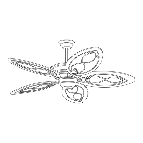
COPA BREEZE
52Ó Wet Location
Ceiling Fan Owner's Manual
Model Number
TB311DBZ00
Distressed Bronze
Net Weight:
24.5
Lbs.
XXXXXXXXXXXXXXXXXXXXXXXXXXXXXXXXXXXXXXXXXXXXXXXXXXXXXXXXXXXXXXXXXXXXXXXXXXXXXXXX
Part No. F40BP74090001
Form No. BP7409-1
Advertisement
Table of Contents

Related Manuals for Tommy Bahama COPA BREEZE TB311DBZ00


Summary of Contents for Tommy Bahama COPA BREEZE TB311DBZ00
- Page 1 READ AND SAVE THESE INSTRUCTIONS XXXXXXXXXXXXXXXXXXXXXXXXXXXXXXXXXXXXXXXXXXXXXXXXXXXXXXXXXXXXXXXXXXXXXXXXXXXXXXXX COPA BREEZE 52Ó Wet Location Ceiling Fan Owner's Manual Model Number TB311DBZ00 Distressed Bronze Net Weight: 24.5 Lbs. XXXXXXXXXXXXXXXXXXXXXXXXXXXXXXXXXXXXXXXXXXXXXXXXXXXXXXXXXXXXXXXXXXXXXXXXXXXXXXXX Part No. F40BP74090001 Form No. BP7409-1...
-
Page 2: Safety Instructions
WARNING WARNING: To avoid fire, shock, and serious personal injury, follow these instructions. Safety Instructions 1. Read your ownerÕs manual carefully and keep it for future reference. 2. Before servicing or cleaning unit, switch power off at service panel and lock service panel disconnecting means to prevent power from being switched on accidentally. -
Page 3: Tools Needed For Assembly
THIS FAN IS SUITABLE FOR WET LOCATIONS SUCH AS PORCHES, PATIOS, AND DECKS. Tools Needed for Assembly Installed Wire Length Wire Size A.W.G. Up to 50 ft. One Phillips head screwdriver One wire stripper 50-100 ft. One stepladder Materials WARNING Wiring, outlet box and box connec- Before assembling your ceiling fan, tors must be of type required by the... -
Page 4: Electrical Requirements
Tommy Bahama chain switch set to its high speed Wall Control. Use only this Tommy setting. -
Page 5: How To Assemble Your Ceiling Fan
If your fan is to replace an existing 3. Separate, untwist and unkink the ceiling light fixture, turn electricity three motor leads. Route the off at the main fuse or circuit break- motor leads through the downrod er box at this time and remove the and seat the downrod in the motor existing light fixture. - Page 6 5. While pulling up on the downrod, tighten the setscrew(s) using a SETSCREW phillips screwdriver (Figure 3). HANGER NOTE: The setscrew must be proper- BALL ly installed as described above, or fan wobble could result. 6. Route the motor leads through the coupler cover onto the downrod DOWNROD CEILING...
- Page 7 18. Place the switch housing plate WARNING onto the motor flange. Rotate the switch housing plate clockwise to To reduce the risk of personal injury, do not bend the blade flanges when engage the two loosened screws installing the flanges, balancing the in the key hole slots.
-
Page 8: How To Hang Your Ceiling Fan
21. Position switch housing How to Hang assembly on the switch housing Your Ceiling Fan plate and align the holes in the switch housing assembly with the WARNING holes in the plate. Reinstall the three screws (previously removed The fan must be hung with at least 7' of in step 19) to secure the switch clearance from floor to blades (Figure 11). - Page 9 CAUTION: To reduce the risk of elec- WARNING trical shock, disconnect the electrical supply circuit before installing the To avoid possible fire or shock, do not pinch wires between the hanger ball/ fan and wall control. downrod assembly and hanger bracket. 2.
- Page 10 CEILING WHITE SUPPLY COVER BLACK SUPPLY (NEUTRAL) (HOT) BLACK FAN WHITE WIRE FAN WIRE SUPPLY BLUE WIRE GROUND WIRE HANGER GREEN WIRE BRACKET (GROUND) FROM THREADED HANGER BALL STUD (2) GREEN WIRE LISTED WIRE (GROUND) FROM 1-1/4" CONNECTOR (3) HANGER BRACKET THREADED STUD LOCKWASHER...
- Page 11 CAUTION: To reduce the risk of elec- TO FAN MOTOR LOAD NEUTRAL trical shock, disconnect the electrical supply circuit before installing the fan and wall control. NOTE: Electric connections should be in accordance with the National Electrical Codes and all Local Codes. Before starting, disconnect power to the circuit at the fuse box or circuit breaker panel.
-
Page 12: Using Your Ceiling Fan
Using Your Ceiling Fan Maintenance IMPORTANT IMPORTANT CARE INSTRUCTIONS Fan installation must be completed, for your Ceiling Fan including the installation of the fan Periodic cleaning of your new ceiling blades, before testing of the controls. fan is the only maintenance that is needed. -
Page 13: Troubleshooting
WARNING: FOR YOUR OWN SAFETY TURN OFF POWER AT FUSE BOX OR CIRCUIT BREAKER BEFORE TROUBLE SHOOTING YOUR FAN. Trouble Shooting TROUBLE PROBABLE CAUSE SUGGESTED REMEDY 1. Fan will not 1. Fuse or circuit breaker 1. Check main and branch start. -
Page 14: How To Order Repair Parts
Repair Parts Before discarding packaging material, be certain all parts have been removed. HOW TO ORDER REPAIR PARTS WHEN ORDERING REPAIR PARTS, ALWAYS GIVE THE FOLLOWING INFORMATION: • PART NUMBER • NAME OF ITEM • PART DESCRIPTION • MODEL NUMBER The model number of your Fan will be found on a label attached to the top housing. - Page 15 Repair Parts Listing Part Number Model No. Description TB311DBZ00 Hanger Pack, Consisting of: 761655-81 Hanger Bracket — Hanger Ball — Downrod — Parts Bag, Containing: 764022 Wire Connector (4) — Knurled Knob, #8-32 (2) — Lockwasher, #8 (2) — Threaded Stud, 1-1/4” (2) —...
-
Page 16: Limited Warranty
LIMITED WARRANTY What The Warranty Covers: This warranty covers the motor and the other components and accessories of your Emerson ceiling fan against all defects in workmanship and materials. You must be the original purchaser or user of the product to be covered. What The Period Of Coverage Is: As it applies to the motor, this warranty will last for a lifetime of your ceiling fan.
Need help?
Do you have a question about the COPA BREEZE TB311DBZ00 and is the answer not in the manual?
Questions and answers