Table of Contents
Advertisement
Quick Links
READ AND SAVE THESE INSTRUCTIONS
xxxxxxxxxxxxxxxxxxxxxxxxxxxxxxxxxxxxxxxxxxxxxxxxxxx
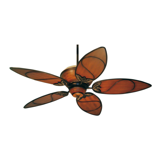
PARADISE KEY
Ceiling Fan
Owner's Manual
Model Number
TB301MAB01
Medium Antique Brown Housing with
Medium Antique Brown Blades
Net Weight:
33.5
Lbs.
xxxxxxxxxxxxxxxxxxxxxxxxxxxxxxxxxxxxxxxxxxxxxxxxxxx
Part No. F40BP72880001
Form No. BP7288-1
Advertisement
Table of Contents

Subscribe to Our Youtube Channel
Related Manuals for Tommy Bahama PARADISE KEY TB301MAB


Summary of Contents for Tommy Bahama PARADISE KEY TB301MAB
- Page 1 READ AND SAVE THESE INSTRUCTIONS xxxxxxxxxxxxxxxxxxxxxxxxxxxxxxxxxxxxxxxxxxxxxxxxxxx PARADISE KEY Ceiling Fan Owner's Manual Model Number TB301MAB01 Medium Antique Brown Housing with Medium Antique Brown Blades Net Weight: 33.5 Lbs. xxxxxxxxxxxxxxxxxxxxxxxxxxxxxxxxxxxxxxxxxxxxxxxxxxx Part No. F40BP72880001 Form No. BP7288-1...
- Page 2 NOTE: This fan is suitable for use with solid-state speed controls. WARNING: To avoid fire, shock or injury, do not use a Tommy Bahama or any other brand of control not specifically approved for this fan. WARNING: This product is designed to use only those parts supplied with this product and/or any accessories designated specifically for use with this product by Emerson Electric Co.
-
Page 3: Tools Needed For Assembly
This Manual Is Designed to Make it as Easy as Possible for You to Assemble, Install, Operate and Maintain Your Ceiling Fan Tools Needed for Assembly Installed Wire Length Wire Size A.W.G. One Phillips head screwdriver Up to 50 ft. One wire stripper 50-100 ft. -
Page 4: Remote Control Procedures
9. Eleven 10-32 x 5/8” oval head proceeding. screws General Remote Control Procedures Your Tommy Bahama ceiling fan comes General equipped with a remote control transmitter Your Tommy Bahama Ceiling Fan/Light and a remote control receiver. This remote Remote Control consists of hand-held trans-... -
Page 5: Installation Of Battery
Preset Memory Feature CEILING FAN PROCEDURES Electrical Requirements Your Tommy Bahama receiver is equipped with a preset memory feature. If the AC sup- ply to the receiver is powered through a wall IMPORTANT: Your ceiling fan will not switch, when the switch is turned OFF, the... -
Page 6: How To Assemble Your Ceiling Fan
How to Assemble Your 4. Align the clevis pin holes in the downrod with the holes in the motor coupling. Install Ceiling Fan the clevis pin and secure with the hairpin clip (Figure 4). (Pin and clip are supplied in 1. - Page 7 SETSCREW KNURLED HANGER BALL KNOB (2) DOWNROD CEILING LOCKWASHER COVER MOTOR COVER 1" THREADED STUD (2) Figure 5 Figure 6 NOTE: Lightly snug the knurled knobs Cut the white, blue, black and yellow and make sure the wires and wire con- leads from the downrod approximately nectors are completely inside the motor 6 to 9-inches above the hanger ball.
-
Page 8: How To Hang Your Ceiling Fan
How to Hang WARNING Your Ceiling Fan To reduce the risk of personal injury, do not bend the blade flanges when installing WARNING the flanges, balancing the blades, or clean- ing the fan. Do not insert foreign objects The fan must be hung with at least 7' of clear- between rotating fan blades. - Page 9 2. Position the top and bottom halves of the 4. Carefully lift the fan from the styrofoam styrofoam packaging side-by-side on the packaging and seat the hanger ball/down- floor with a three or four-inch gap between rod assembly on the hanger bracket that them (Figure 11).
-
Page 10: How To Wire Your Ceiling Fan
How to Wire Your Ceiling Fan If you feel that you do not have enough 2. Position the RCK55 Receiver in the ceiling electrical wiring knowledge or experi- cover so that the flat side of the receiver ence, have your fan installed by a faces up and the open portion of the receiv- licensed electrician. - Page 11 RCK55 RECEIVER 110V SUPPLY BLACK SUPPLY WIRE WHITE RECEIVER WIRE BLACK RECEIVER WIRE WHITE SUPPLY WIRE BLACK/WHITE RECEIVER WIRE BLUE RECEIVER WIRE WHITE FAN WIRE YELLOW RECEIVER WIRE BLUE FAN WIRE BLACK FAN WIRE YELLOW FAN WIRE DOWNROD Figure 15 6.
- Page 12 7. Slide the receiver up and over the hanger 9. Hold the switch housing cover over the bracket. Press the receiver against the ceil- switch housing and carefully rotate the cover ing, then slide the ceiling cover up to the until the notches on the inside of the cover threaded studs and turn until the studs engage with the detents on the switch hous-...
-
Page 13: Attaching Light Kit
( ) button on the remote control. The fan must be operating at any To install a Tommy Bahama accessory light speed for the reverse button to function. fixture, remove the finial nut and cover trim, The blades will turn in the opposite direc- then remove the two screws securing the switch tion and reverse the airflow (Figure 21). -
Page 14: Maintenance
Maintenance Accessories 1. Ceiling Fan Light Kits (see store or catalog). IMPORTANT CARE INSTRUCTIONS for your Ceiling Fan 2. Downrod Extension Kits (see store or cata- log). Periodic cleaning of your new ceiling fan is the 3. Ceiling Fan Remote Controls (see store or only maintenance that is needed. -
Page 15: Troubleshooting
WARNING: FOR YOUR OWN SAFETY TURN OFF POWER AT FUSE BOX OR CIRCUIT BREAKER BEFORE TROUBLE SHOOTING YOUR FAN. Trouble Shooting TROUBLE PROBABLE CAUSE SUGGESTED REMEDY 1. Fan will not 1. Fuse or circuit breaker 1. Check main and branch start. -
Page 16: How To Order Repair Parts
Repair Parts Before discarding packaging material, be certain all parts have been removed. HOW TO ORDER REPAIR PARTS WHEN ORDERING REPAIR PARTS, ALWAYS GIVE THE FOLLOWING INFORMATION: • PART NUMBER • NAME OF ITEM • PART DESCRIPTION • MODEL NUMBER The model number of your Fan will be found on a label attached to the top housing. - Page 17 Repair Parts Listing Part Number Model No. Description TB301MAB01 Hanger Pack, Consisting of: 761655-41 Hanger Bracket — Hanger Ball — Downrod — Parts Bag, Containing: 762766 Wire Connector (6) — Setscrew Wrench, 5/32” — Knurled Knob, 8-32 (4) — Lockwasher, #8 (4) —...
-
Page 18: Instruction To The User
INSTRUCTION TO THE USER (if device contains a digital device) This equipment has been tested and found to comply with the limits for a Class B digital device, pur- suant to part 15 of the FCC Rules. These limits are designed to provide reasonable protection against harmful interference in a residential installation. - Page 19 Notes...
-
Page 20: Limited Warranty
LIMITED WARRANTY What The Warranty Covers: This warranty covers the motor and the other components and accessories of your Emerson ceiling fan against all defects in workmanship and materials. You must be the original purchaser or user of the product to be covered. What The Period Of Coverage Is: As it applies to the motor, this warranty will last for a lifetime of your ceiling fan.
Need help?
Do you have a question about the PARADISE KEY TB301MAB and is the answer not in the manual?
Questions and answers