Table of Contents
Advertisement
IMPORTANT, RETAIN FOR FUTURE REFERENCE:
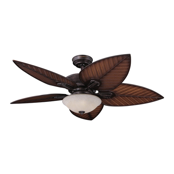
Cabrillo Cove Ceiling Fan with
Tropical Blades
Questions, problems, missing parts? Before returning to the store call Emerson Customer Service
Installation - 2 people
recommended, could
take up to several hours
Part No. F40BP74650000
Revision - 130422
READ CAREFULLY
Tommy Bahama
INDOOR/OUTDOOR
52 in. / 132 cm.
CABRILLO COVE
CEILING FAN
Net Weight:
31.0
lb. /
8 a.m. - 8 p.m., CST, Monday - Friday
8 a.m. - 5 p.m., CST, Saturday - Sunday
1-800-875-3545
Email Help - email@carrollparts.com
14.1
kg.
ITM./ART. 702146
Cabrillo Cove Ceiling Fan with
Paddle Blades
Form No. BP7465
Model No.: TB135
Advertisement
Table of Contents
Troubleshooting

Related Manuals for Tommy Bahama CABRILLO COVE


Summary of Contents for Tommy Bahama CABRILLO COVE
-
Page 1: Ceiling Fan
ITM./ART. 702146 IMPORTANT, RETAIN FOR FUTURE REFERENCE: READ CAREFULLY Cabrillo Cove Ceiling Fan with Cabrillo Cove Ceiling Fan with Paddle Blades Tropical Blades Tommy Bahama INDOOR/OUTDOOR 52 in. / 132 cm. CABRILLO COVE CEILING FAN Net Weight: 31.0 14.1 lb. / Questions, problems, missing parts? Before returning to the store call Emerson Customer Service 8 a.m. -
Page 2: Table Of Contents
Warranty ..............44 Tommy Bahama • 04/2013... -
Page 3: Safety Warning
The date code of this fan may be found on the box, stamped in ink on a white label. You should record this data above and keep it in a safe place for future use. Tommy Bahama • 04/2013 email@carrollparts.com • 1-800-875-3545... -
Page 4: Preparation
1. Preparation Thank You for Your Purchase Use of This Manual Your Tommy Bahama Ceiling Fan is the right choice for Read the entire manual before installation. This manual your home or office. We take pride in providing you with will help you install, operate and maintain your ceiling fan. -
Page 5: Ceiling Fan Location
Use the Supplied 18 in. / 45.7 cm. Downrod For Installation For Installation Your Tommy Bahama Ceiling Fan is designed for flat, On flat high ceilings, use the 18 in. / 45.7 cm. downrod standard 8 ft. / 2.4 m. ceilings, even when a light kit is (supplied) to achieve the optimum installation height. -
Page 6: Electrical Requirements
Tommy Bahama remote control. Use only the Tommy Bahama remote control and a WARNING listed general use on/off wall switch. -
Page 7: How To Assemble Your Ceiling Fan
2.7 m. The 18 in. / 45.7 cm. downrod is usable only when your ceiling height is 9 ft. / 2.7 m. or higher. 1.4 in. x 0.3 in. / 3.5 cm. x 0.6 cm. Tommy Bahama • 04/2013 email@carrollparts.com • 1-800-875-3545... - Page 8 The motor wires may cause some interference and it may The hairpin clip must be properly installed to prevent the take several attempts to push the pin through both side of clevis pin from working loose. the downrod. 2b or 3 Tommy Bahama • 04/2013 email@carrollparts.com • 1-800-875-3545...
- Page 9 4 . it rests on top of the coupler cover 6 . Be sure the ceiling cover is oriented correctly, with the large opening facing upward. 2b or 3 2b or 3 Tommy Bahama • 04/2013 email@carrollparts.com • 1-800-875-3545...
- Page 10 It is critical that the pin in the hanger ball is properly installed and the setscrew securely tightened. Failure to verify that the pin and setscrew are properly installed could result in the fan falling. Tommy Bahama • 04/2013 email@carrollparts.com • 1-800-875-3545...
- Page 11 18 using a phillips screwdriver. Securely tighten the screws. NOTE: Be sure the plain side of the ceiling fan blade is x 16 facing up. Repeat this procedure for the remaining four blades. Tommy Bahama • 04/2013 email@carrollparts.com • 1-800-875-3545...
- Page 12 Phillips tighten all ten blade assembly screws to the motor hub in a screwdriver through the viewing window and loosely clockwise rotation. tighten both blade holder screws. This completes the blade installation. Tommy Bahama • 04/2013 email@carrollparts.com • 1-800-875-3545...
-
Page 13: How To Remove The Light Kit From The Fan
Loosen and remove the hex nut h with a 14 mm. end Connection") and the two white wires (labeled "For Light Kit Connection"). Retain the wire connectors 10c for wrench, and the lockwasher i . Retain both for the next future use. step. Tommy Bahama • 04/2013 email@carrollparts.com • 1-800-875-3545... - Page 14 Firmly attach the screw into the bottom #8-32 x 0.3 in. / 0.8 cm. flat head screws 22 from switch threaded hole of the switch cover using a phillips housing plate j and retain for future installation. screwdriver. Tommy Bahama • 04/2013 email@carrollparts.com • 1-800-875-3545...
- Page 15 Section 6 and proceed to Section 7. WARNING To avoid possible fire or shock, do not pinch wires between the switch cover and the switch housing plate. Tommy Bahama • 04/2013 email@carrollparts.com • 1-800-875-3545...
-
Page 16: How To Assemble Your Light Kit
Make sure the connector latch closes to properly lock both pieces together. To avoid possible fire or shock, do not pinch wires between the switch housing/light kit assembly and the switch housing plate. Tommy Bahama • 04/2013 email@carrollparts.com • 1-800-875-3545... -
Page 17: How To Assemble Your Light Kit
Securely reinstall the three previously removed Installation of the light kit assembly 10 is now complete, #8-32 x 0.3 in. / 0.8 cm. pan head screws into the proceed to Section 7. aligned holes with a phillips screwdriver. Tommy Bahama • 04/2013 email@carrollparts.com • 1-800-875-3545... -
Page 18: How To Hang Your Ceiling Fan
Consult a qualified electrician if in doubt. Disconnect electrical power to the branch circuit at the circuit breaker or fuse box before attempting to install the ceiling fan hanger bracket on the outlet box. Tommy Bahama • 04/2013 email@carrollparts.com • 1-800-875-3545... -
Page 19: How To Hang Your Ceiling Fan
Failure to lock the anti-rotation tab in the hanger ball groove could cause damage to electrical wires and possible shock or fire hazard. WARNING To avoid possible fire or shock, do not pinch wires between the hanger ball and hanger bracket. Tommy Bahama • 04/2013 email@carrollparts.com • 1-800-875-3545... -
Page 20: How To Wire Your Ceiling Fan
Position the supply wires to the left side of the outlet box n and position the fan wires to the right side as shown. SUPPLY WIRES WIRES Tommy Bahama • 04/2013 email@carrollparts.com • 1-800-875-3545... - Page 21 Gently pull on the connector to ensure it is firmly tightened onto the wires and will not fall off. Tommy Bahama • 04/2013 email@carrollparts.com • 1-800-875-3545...
- Page 22 Gently pull on the connector to ensure it is firmly tightened technique described in 8.4. onto the wires and will not fall off. Gently pull on the connector to ensure it is firmly tightened onto the wires and will not fall off. Tommy Bahama • 04/2013 email@carrollparts.com • 1-800-875-3545...
- Page 23 After wire connections have been made, separate the grounded white neutral and green wires on one side of the outlet box from the ungrounded black and blue wires on the other side of the outlet box n . Tommy Bahama • 04/2013 email@carrollparts.com • 1-800-875-3545...
- Page 24 WHITE WHITE (NEUTRAL) BLACK (TO GROUND MOTOR L) TWO-CONDUCTOR WHITE (TO MOTOR N) CABLE (WITH BLUE (FOR LIGHT) GROUND) BLACK GREEN WIRE (GROUND) BLUE FROM HANGER BALL AND WHITE HANGER BRACKET HANGER BALL Tommy Bahama • 04/2013 email@carrollparts.com • 1-800-875-3545...
-
Page 25: Installation Of The Ceiling Cover
WARNING To avoid possible fire or shock, make sure that antenna wire is not pinched between the ceiling cover and the ceiling. Tommy Bahama • 04/2013 email@carrollparts.com • 1-800-875-3545... - Page 26 15 and loosely tighten to keep the cover in place. Install the other lockwasher and knurled knob onto the second threaded stud. Tighten both knurled knobs securely until the ceiling cover fits snugly against the ceiling. Tommy Bahama • 04/2013 email@carrollparts.com • 1-800-875-3545...
-
Page 27: Installation Of Glass Shade
Turn the hex nut with your fingers until it is as tight as possible. Do not use a wrench to tighten the nut, the glass could break if too much force is used. Tommy Bahama • 04/2013 email@carrollparts.com • 1-800-875-3545... - Page 28 NOTE: Periodically check that the glass bowl is seated correctly onto the light kit upper cover plate and the hex nut and finial nut are tightly fastened. Tommy Bahama • 04/2013 email@carrollparts.com • 1-800-875-3545...
-
Page 29: Transmitter Battery Installation And Code Setting
11. Transmitter Battery Installation and Code Setting 11.1 Your Tommy Bahama Ceiling Fan is equipped with a Remote Control system consisting of a hand-held transmitter and a receiver which was previously installed in High Section 8. The remote control transmitter is powered by a 9-volt alkaline battery. - Page 30 "X" position to turn the dimming feature off. 11.4 INSTALLATION OF THE BATTERY Reach inside the battery compartment and gently extend the battery connector harness r outside the compartment for connection with the 9-volt battery 12e . Tommy Bahama • 04/2013 email@carrollparts.com • 1-800-875-3545...
- Page 31 High the mating lock. The assembly of your ceiling fan is nearly complete, proceed to the next section to pair the transmitter with the receiver. Tommy Bahama • 04/2013 email@carrollparts.com • 1-800-875-3545...
-
Page 32: Receiver Code Leaning - Programming The Operating Frequency Of The Receiver
You may need to change your location in the room when pushing the "OFF" button to enable the receiver to catch the programming signal. 12.3 Programming the receiver is now complete, proceed to Section 13 and learn how to operate the ceiling fan. Tommy Bahama • 04/2013 email@carrollparts.com • 1-800-875-3545... -
Page 33: Operation Of Remote Control
PRESET MEMORY FEATURE good. Your Tommy Bahama ceiling fan receiver is equipped with a preset memory feature. If the AC power supply to the receiver is powered OFF at the wall switch, the receiver will store the light intensity and fan speed in memory until the wall switch is turned ON again. -
Page 34: Installation Of The Storage Bracket
12f . Note the cover has a dovetail edge and will 12d into the wall using a phillips head screw driver. only insert into the bracket when oriented correctly. Tommy Bahama • 04/2013 email@carrollparts.com • 1-800-875-3545... -
Page 35: Using Your Ceiling Fan
4. One 1/4-20 x 0.5 in. / 1.3 cm. pan head shoulder screw 20 with integrated washer 21 . 5. One #8-32 x 0.3 in. / 0.8 cm. flat head screw 22 . 6. Three small yellow wire connectors 12c . Tommy Bahama • 04/2013 email@carrollparts.com • 1-800-875-3545... -
Page 36: Using Your Ceiling Fan
15. Using Your Ceiling Fan (Continued) 15.4 Assembly of the ceiling fan is now complete. Tommy Bahama • 04/2013 email@carrollparts.com • 1-800-875-3545... -
Page 37: Interchanging Fan Blades On Installed Fan
7 or 8 from the blade holder 9 and safely store it. a #2 phillips screw driver to secure the blades to the holders. Retain the screws for installation of the new blade. Tommy Bahama • 04/2013 email@carrollparts.com • 1-800-875-3545... -
Page 38: Interchanging Fan Blades On Installed Fan
Carefully store the removed blades for future use. and operating correctly. If your fan wobbles, it maybe maybe necessary to use the balance kit supplied in the hardware kit. Follow the balance kit instructions to preform the balancing procedure. Tommy Bahama • 04/2013 email@carrollparts.com • 1-800-875-3545... -
Page 39: Trouble Shooting
2. Remote control battery is weak. 2. Replace the 9 volt remote battery. 3. The lamps are burnt out. 3. Replace the lamps. Tommy Bahama • 04/2013 email@carrollparts.com • 1-800-875-3545... -
Page 40: Remote Control Trouble Shooting
18.3 BATTERY RECYCLING AND DISPOSAL Safely recycle or dispose of the used battery in accordance with local regulations. Proceed to Section 13 and learn how to operate the ceiling fan. Tommy Bahama • 04/2013 email@carrollparts.com • 1-800-875-3545... -
Page 41: Maintenance
This Class B digital apparatus meets all requirements of the Canadian Interference-Causing Equipment Regulations. Tommy Bahama • 04/2013 email@carrollparts.com • 1-800-875-3545... -
Page 42: Repair Parts
Please see page 43 for parts table. These parts numbers shown below do not correspond to the assembly instruction identification numbers found within this manual and parts/hardware guide. Use these part numbers only when ordering repair parts High Tommy Bahama • 04/2013 email@carrollparts.com • 1-800-875-3545... - Page 43 PART NUMBER • PART DESCRIPTION • NAME OF ITEM • MODEL NUMBER The model number of your Fan will be found on a label attached to the top housing. For repair parts, phone 1-800-875-3545. Tommy Bahama • 04/2013 email@carrollparts.com • 1-800-875-3545...
-
Page 44: Warranty
Limited Warranty What The Warranty Covers: This warranty covers the motor and the other components and accessories of your Emerson ceiling fan against all defects in workmanship and materials. You must be the original purchaser or user of the product to be covered. What The Period Of Coverage Is: As it applies to the motor, this warranty will last for a lifetime of your ceiling fan.
Need help?
Do you have a question about the CABRILLO COVE and is the answer not in the manual?
Questions and answers