
Subscribe to Our Youtube Channel
Related Manuals for ParaBody 827 LAT MACHINE


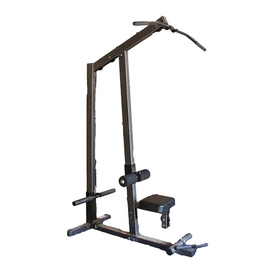
Summary of Contents for ParaBody 827 LAT MACHINE
- Page 1 827 LAT MACHINE WARNING: Read and follow all directions for each step to insure proper assembly of this product. USER’S GUIDE CLASS H Version: 827108 PART # 7302801 Revision: 06/14/02 REV. A...
-
Page 2: Important Safety Information
3. Keep body and clothing free of all moving objects. DO NOT attempt to fix. Notify your authorized ParaBody dealer before use and have repairs made by 4. Inspect the machine before use. DO NOT use it if it an authorized service technician. -
Page 3: Important Notes
IMPORTANT NOTES Please note: * Thank you for purchasing the ParaBody LAT MACHINE. Please read these instructions thoroughly and keep them for future reference. This product must be assembled on a flat, level surface to assure its proper function. * This product must be assembled on a flat, level surface to assure its proper function. DO NOT securely tighten any frame connections until the entire frame has been assembled, unless otherwise stated. - Page 4 1’ 2’ 3’ 4’ 5’ 1’ 2’ 3’ 4’ 5’ 1 Square = 1’ X 1’ Minimum Required Usable Space Length = 82 inches (208.5 cm) 6’ 10” Width = 71 inches (180.5 cm) 5’11” Height = 83 inches (211 cm) 6’ 11” Dimensions Including Leg Press (optional) Length = 82 inches (208.5 cm) 6’...
-
Page 5: Parts List
PARTS LIST DESCRIPTION PART # PART # DESCRIPTION BASE 6759109 6590801 L E A 3 X 2” INSERT GUIDE FRONT UPRIGHT 6758909 6387901 5” VINYL CAP L E A REAR UPRIGHT 6760209 L E A 3105401 STARLOCK COLLAR TOP BOOM 6760109 3116001 L E A... - Page 6 32 1/2 X 3” FIGURE 1 STEP 1: • Attach two 2” SQ. COVER CAPS (18) onto the ends of the REAR UPRIGHT (3) as shown in FIGURE 1. • Insert two 3 X 2” END CAPS (19) into the ends of the BASE (1) and REAR UPRIGHT (3) as shown in FIGURE 1. •...
- Page 7 FIGURE 2 STEP 2: • Attach eight 1 X 1” GLIDES (39) to the ends the CARRIAGE (5) as shown in FIGURE 2 using the following steps: • Thoroughly clean all surfaces where the 1 X 1” GLIDES (39) are to be attached. •...
- Page 8 33 1/2 X 4” FIGURE 4 STEP 4: • Insert two 2” SQ. END CAPS (17) into the FRONT UPRIGHT (2) as shown in FIGURE 4. • LOOSELY assemble the FRONT UPRIGHT (2) to the BASE (1) using two 1/2 X 4” BOLTS (33) and two 1/2” LOCK NUTS (28). See FIGURE 4.
- Page 9 FIGURE 5 STEP 5: • CAREFULLY slide the ROLLER PAD SUPPORT (6) over into the FRONT UPRIGHT (2) and engage the SPRING PIN into one of the adjustment holes. See FIGURE 5. • CAREFULLY slide the CARRIAGE (5) over into the REAR UPRIGHT (3) as shown in FIGURE 5.
- Page 10 33 1/2 X 4” 32 1/2 X 3” TIGHTEN! TIGHTEN! 30 3/8 X 2-3/4 FIGURE 6 STEP 6: • LOOSELY assemble the TOP BOOM (4) to the FRONT UPRIGHT (2) using one 1/2 X 3” BOLT (32), two 1/2” WASHERS (27), and one 1/2”...
- Page 11 30 3/8 X 2-3/4” FIGURE 7 STEP 7: • Route the CABLE (12) through the TOP BOOM (4) as shown in FIGURE 7. • SECURELY assemble three 3-1/2” PULLEYS (14) to the slots in TOP BOOM (4) using three 3/8 X 2-3/4” BOLTS (30), six 3/8” FLANGE SPACERS (34), and three 3/8”...
- Page 12 29 3/8 X 2-1/4” !IMPORTANT! SECURELY TIGHTEN FIGURE 8 STEP 8: • Attach the CABLE (12) from the TOP BOOM (4) to the CARRIAGE (5) using one QUICK LINK (37) as shown in FIGURE 8. (IMPORTANT! Securely tighten QUICK LINK.) •...
- Page 13 30 3/8 X 2-3/4” FIGURE 9 STEP 9: • Securely assemble the ball end of the CABLE (12) and two 3-1/2” PULLEYS (14) to the FRONT UPRIGHT (2) using four 3/8 X 2-3/4” BOLTS (30), four 3/8” FLANGE SPACERS (34), four 3/8” WASHERS (25), and four 3/8” LOCKNUTS (26). (NOTE: The CABLE (12) should be routed between the pulley and the retaining bolts as shown in FIGURE 9.)
- Page 14 29 3/8 X 2-1/4” 31 3/8 X 4” FIGURE 10 STEP 10: • Loop the CABLE (12) over one 4-1/2” PULLEY (15) as shown in FIGURE 10. • SECURELY the 4-1/2” PULLEY (15) to the 1/4 X 2 X 7-1/4” PLATES (9) using one 3/8 X 2-1/4” BOLT (29), two 3/8” WASHERS (25), and one 3/8”...
- Page 15 FIGURE 11 STEP 11: • Attach the LAT BAR (7) to the ball end of the upper CABLE (12) using one 5/16” SNAP LINK (36) as shown in FIGURE 11. • Attach the LOW ROW BAR (8) to the ball end of the lower CABLE (12) using one 12-LINK CHAIN (38) and two 5/16” SNAP LINKS (36) as shown in FIGURE 11.
-
Page 16: Maintenance
Please note: * We recommend cleaning your product (pads and frame) on a regular basis, using warm soapy water. Touch-up paint can be purchased from your ParaBody customer service representative at (800) 328-9714. * Inspect equipment daily. Tighten all loose connections are replace worn parts immediately. -
Page 17: Limited Warranty
ParaBody extends the following LIMITED WARRANTY to the original owner of the ParaBody products. The Warranty terms apply to IN HOME USE ONLY. 1. LIMITED WARRANTY ON FRAME AND WELDS. If the frame of the ParaBody product or a weld should crack or break, it will be repaired or replaced by ParaBody. -
Page 18: International Offices
LIFE FITNESS 14150 Sunfish Lake Blvd. Ramsey Minnesota, 55303 U.S.A. Tel: 763.323.4500 Fax: 763.323.4797 800.328.9714 (Toll-free within the U.S. and Canada) www.parabody.com INTERNATIONAL OFFICES Life FitnessAtlantic BV Life Fitness (UK) Ltd. Atlantic Headquarters Queen Adelaide Bijdorpplein 25-31 Ely, Cambs CB7 4UB...
Need help?
Do you have a question about the 827 LAT MACHINE and is the answer not in the manual?
Questions and answers