TracVision M3 User Manual
Satellite tv antenna system
Hide thumbs
Also See for TracVision M3:
- Installation manual (17 pages) ,
- Installation manual (15 pages) ,
- Instructions manual (9 pages)
Table of Contents
Advertisement
Advertisement
Table of Contents

Related Manuals for TracVision TracVision M3


Summary of Contents for TracVision TracVision M3
- Page 1 TracVision M3 – DX Version Linear Configuration...
- Page 2 DX Version - Linear User’s Guide This user’s guide provides all of the basic information you need to operate, set up, and troubleshoot the TracVision M3 satellite TV antenna system. For detailed system installation information, please refer to the TracVision M3 Installation Guide.
- Page 3 TracVision and KVH are registered trademarks of KVH Industries, Inc. The unique light-colored dome with dark contrasting base is a registered trademark of KVH Industries, Inc. DVB (Digital Video Broadcasting) is a registered trademark of the DVB Project. All other trademarks are the property of their respective owners.
-
Page 4: Table Of Contents
TracVision M3 User’s Guide Table of Contents Table of Contents Introduction Using this Manual ................3 TracVision M3 System Overview............5 Linear Satellite Signals ..............6 Operation Receiving Satellite TV Signals............11 Turning the System On/Off ..............12 System Startup ................13 Understanding the Status Screen ............15 Switching Satellites .................16... - Page 5 TracVision M3 User’s Guide Table of Contents Viewing System Information ............46 Changing the Satellite Switching Mode ...........49 Calibrating the Gyros ...............51 Changing Tracking Parameters ............53 Technical Support................57 Product Care ..................58 Wiring Diagram Wiring Diagram ................61 Menus Quick Reference Guide Interface Box Menus ................65 Programming User-Defined Satellites Connecting a Laptop to the Antenna..........69...
- Page 6 TracVision M3 User’s Guide Chapter 1 - Introduction 1. Introduction This chapter provides a basic overview of this manual and your TracVision system. Contents Using this Manual.............. 3 TracVision M3 System Overview ........5 Linear Satellite Signals............6...
-
Page 7: Introduction
TracVision M3 User’s Guide Chapter 1 - Introduction Using this Manual This manual provides complete operation, setup, and troubleshooting information for your TracVision system. Who Should Use This Manual The user should refer to the “Operation” and “System Preferences” chapters to learn how to operate the system using the interface box. - Page 8 TracVision M3 User’s Guide Chapter 1 - Introduction Typographical Conventions This manual uses the following typographical conventions: Text Example Description Press MENUS to view Both the icon and the name of the the menu button are provided. SELECT SATELLITES Text as it appears on the interface box...
-
Page 9: Tracvision M3 System Overview
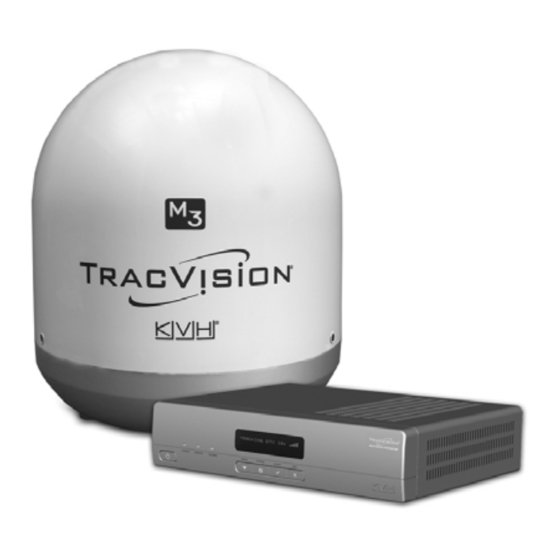
TracVision M3 User’s Guide Chapter 1 - Introduction TracVision M3 System Overview Your TracVision M3 system is a state-of-the-art, actively stabilized antenna system that delivers live satellite TV to your vessel’s audio/ video entertainment system. A basic system is illustrated below. A receiver wiring diagram is provided in Appendix A on page 59. -
Page 10: Linear Satellite Signals
TracVision M3 User’s Guide Chapter 1 - Introduction Linear Satellite Signals Your TracVision system is configured to receive linearly polarized satellite signals. Satellites around the world (with the exception of satellites in North America, which transmit circularly polarized signals) transmit linear signals in vertical and horizontal “waves” that are offset exactly 90º... - Page 11 TracVision M3 User’s Guide Chapter 1 - Introduction The correct skew setting varies depending on your geographic location, since the orientation of your antenna to the satellite changes as you move. For example, as shown in the figure below, if your...
-
Page 12: Operation
Chapter 2 - Operation 2. Operation This chapter explains how to use the interface box to operate the TracVision system. It explains how to turn the TracVision system on or off, interpret the startup screens, and switch between satellites. Contents Receiving Satellite TV Signals ......... -
Page 13: Receiving Satellite Tv Signals
Equator In addition, since TV satellites are located above the equator, the TracVision antenna must have a clear view of the sky to receive satellite TV signals. Anything that stands between the antenna and the satellite can block the signal, resulting in lost reception. Common causes of blockage include trees, buildings, and bridges. -
Page 14: Turning The System On/Off
POWER switch. Turning On the System Follow the steps below to turn on your TracVision system. 1. Make sure the antenna has a clear view of the sky. 2. Turn on your satellite TV receiver and TV. -
Page 15: System Startup
TracVision M3 User’s Guide Chapter 2 - Operation System Startup The display shows the following screens during startup. Interface Box Screen Description Interface box software version KVH INTERFACE BOX VERSION X.YZ Antenna model and main KVH TRACVISION M3 software version SYS SW VERSION X.YZ... - Page 16 TracVision M3 User’s Guide Chapter 2 - Operation Warning Messages on Startup During startup, make sure none of the following warning messages appear on the display. If one of these messages appears, you may need to change your antenna setup to select a different set of satellites (see “Resetting the System to Change Setup”...
-
Page 17: Understanding The Status Screen
TracVision M3 User’s Guide Chapter 2 - Operation Understanding the Status Screen Following startup, the interface box display shows the current system status. Figure 2-4 Interface Box Status Screen ASTRA1 Satellite Signal Strength Screen Field Description Satellite that the antenna is currently tracking... -
Page 18: Switching Satellites
Chapter 2 - Operation Switching Satellites If your TracVision system is set up to track multiple satellites, you can easily switch between them. For normal operation, keep the system set to Automatic satellite switching (factory default). If you wish to manually switch between satellites, see “Changing the Satellite... - Page 19 TracVision M3 User’s Guide Chapter 2 - Operation 2. Press ACCEPT. 3. Press CHANGE until the display shows the correct polarization and band for the desired channel. POLARIZATION/BAND=HL CHANGE ACCEPT There are four possible combinations of polarization/band: Code Polarization Band...
-
Page 20: System Preferences
TracVision M3 User’s Guide Chapter 3 - System Preferences 3. System Preferences This chapter explains how to change the settings for display brightness and latitude/longitude. Refer to “Interface Box Menus” on page 65 for a quick reference guide to accessing these functions within the menu. -
Page 21: Adjusting The Display Brightness
TracVision M3 User’s Guide Chapter 3 - System Preferences Adjusting the Display Brightness Follow the steps below to adjust the brightness of the interface box display. 1. Press MENUS until the display shows “BRIGHTNESS.” BRIGHTNESS= HIGH NEXT MENU CHANGE 2. Press CHANGE until the display shows the desired setting: HIGH, MEDIUM, or LOW. -
Page 22: Entering Latitude/Longitude
TracVision M3 User’s Guide Chapter 3 - System Preferences Entering Latitude/Longitude Follow the steps below to enter your vessel’s latitude and longitude into the system. The antenna will use your position information to speed up satellite acquisition. (If the antenna knows where you are located, it knows where it should start looking for the satellite.) The... - Page 23 TracVision M3 User’s Guide Chapter 3 - System Preferences 3. Press CHANGE again. A cursor appears under the first number in the displayed latitude. LAT/LONG= 41N, 071W CHANGE ACCEPT 4. Press CHANGE until the number is set to the first digit of your vessel’s current latitude.
-
Page 24: Setup
Chapter 4 - Setup 4. Setup When you turn on the TracVision system for the first time, the interface box display shows “SYSTEM NEEDS SETUP.” This chapter explains how to set up your TracVision system for the satellite(s) you wish to track. -
Page 25: Selecting Satellites To Track
TracVision M3 User’s Guide Chapter 4 - Setup Selecting Satellites to Track Follow the steps below to set up the TracVision system to track the satellites of your choice. NOTE: If the status screen does not show “System Needs Setup,” follow the steps in “Resetting the System to Change Setup”... - Page 26 TracVision M3 User’s Guide Chapter 4 - Setup 3. Press CHANGE until the number at the cursor is set to the first digit of your vessel’s latitude. LAT/LONG= 51N, 071W CHANGE ACCEPT 4. Press ACCEPT. The cursor moves to the next number.
- Page 27 (primary) satellite you want to install. SAT 1= HOTBIRD? CHANGE ACCEPT NOTE: The display might show additional satellites not listed above. However, at this time, the TracVision M3 system supports only the satellites specified above. 8. Press ACCEPT. SAT 2= NONE?
- Page 28 TracVision M3 User’s Guide Chapter 4 - Setup 9. Repeat steps 7 and 8 for the remaining satellites you want to install. If you don’t need to install four satellites, select NONE instead. Once you have selected all four satellites, or you have selected NONE, the antenna installs the selected satellite(s) then restarts.
-
Page 29: Setting The Lnb Skew Angle
CHECK LNB SETTING 2. Turn off and unplug your satellite TV receiver. 3. Press the POWER switch on the front of the TracVision interface box to turn off the TracVision system. Make sure the VOLTAGE light goes out. CAUTION Disconnect power from the antenna before you remove the radome. - Page 30 TracVision M3 User’s Guide Chapter 4 - Setup 5. Carefully remove the radome and set it aside in a safe place. Figure 4-3 Removing the Radome 6. Locate the LNB on the back of the antenna reflector. Figure 4-4 Location of LNB on Back of Antenna Reflector...
- Page 31 TracVision M3 User’s Guide Chapter 4 - Setup 7. Loosen the two wing screws securing the LNB to the choke feed. Figure 4-5 LNB Skew Angle Adjustment Choke Feed Skew Arrow Wing Screw (1 of 2) 8. Adjust the LNB, clockwise or counter-clockwise, until the skew arrow on the LNB points to the correct skew angle on the choke feed.
-
Page 32: Resetting The System To Change Setup
TracVision M3 User’s Guide Chapter 4 - Setup Resetting the System to Change Setup If you need to change the antenna’s setup to track a different satellite, follow the steps below to reset the system. Once the system has reset to its factory condition, you will be able to complete an initial setup as described earlier in this chapter. -
Page 33: System Reset
TracVision M3 User’s Guide Chapter 4 - Setup 4. Press CHANGE until the display shows “SYSTEM RESET= YES.” SYSTEM RESET= YES? CHANGE ACCEPT 5. Press ACCEPT. RESET TO FACTORY? ACCEPT EXIT 6. Press ACCEPT again to reset the system. Wait one minute for system startup. -
Page 34: Troubleshooting
TracVision M3 User’s Guide Chapter 5 - Troubleshooting 5. Troubleshooting This chapter identifies basic problems along with their possible causes and solutions. It also explains what the status lights indicate, how to use the diagnostic functions, and how to get technical support. -
Page 35: Five Simple Checks
Five Simple Checks If you are experiencing a problem receiving satellite TV with your TracVision system, first check the five simple things below. If none of these are the problem, check the status lights on the interface box and/ or perform a diagnostics test, as explained later in this chapter. -
Page 36: System Status Lights
TracVision M3 User’s Guide Chapter 5 - Troubleshooting System Status Lights Three status lights on the front of the receiver indicate the current status of the system and can help you identify problems. Figure 5-1 System Status Lights During normal operation, all three status lights should be lit green. - Page 37 TracVision M3 User’s Guide Chapter 5 - Troubleshooting RECEIVER Light The table below explains what the RECEIVER light indicates. Light is... Indicates Description Green Good communications with receiver Orange No comm No communications with receiver; receiver is off or disconnected...
-
Page 38: Running The Diagnostics Test
TracVision M3 User’s Guide Chapter 5 - Troubleshooting Running the Diagnostics Test In addition to the front panel status lights, the interface box includes a self-test function within its Diagnostics menu. Follow the steps below to run this test. 1. Press MENUS until the display shows “DIAGNOSTICS.”... - Page 39 TracVision M3 User’s Guide Chapter 5 - Troubleshooting 4. Press MENUS until the display shows “RUN TEST.” RUN TEST= NO NEXT MENU CHANGE 5. Press CHANGE until the display shows “RUN TEST= YES.” RUN TEST= YES? CHANGE ACCEPT 6. Press ACCEPT to begin the test.
- Page 40 TracVision M3 User’s Guide Chapter 5 - Troubleshooting Diagnostics Test Results The table below lists all of the status messages. Status Message Description Antenna status: Idle, Initializing, ANTENNA: TRACKING Searching, Tracking, or Error PRESS TO CONTINUE Name of the currently selected...
- Page 41 TracVision M3 User’s Guide Chapter 5 - Troubleshooting Status Message Description Input voltage (DC power): SYSTEM DC: OK,12.3 OK: 10-16 VDC PRESS TO CONTINUE Low: 9-10 VDC Bad: Less than 9 VDC or more than 16 VDC Antenna voltage (DC power) ANTENNA DC: OK,41.0...
-
Page 42: Viewing System Information
TracVision M3 User’s Guide Chapter 5 - Troubleshooting Viewing System Information You can view the TracVision system’s software versions and serial numbers on the interface box display. Follow the steps below to display the system information. 1. Press MENUS until the display shows “DIAGNOSTICS.”... - Page 43 TracVision M3 User’s Guide Chapter 5 - Troubleshooting 4. Press MENUS until the display shows “SHOW SYS INFO.” SHOW SYS INFO= NO NEXT MENU CHANGE 5. Press CHANGE until the display shows “SHOW SYS INFO= YES.” SHOW SYS INFO= YES?
- Page 44 TracVision M3 User’s Guide Chapter 5 - Troubleshooting System Information The table below lists all of the system information reported by the interface box. Information Message Description Model of TracVision antenna TRACVISION M3 (M3) PRESS TO CONTINUE Version of antenna main software SYS SW: 1.2...
-
Page 45: Changing The Satellite Switching Mode
TracVision M3 User’s Guide Chapter 5 - Troubleshooting Changing the Satellite Switching Mode During normal operation, the antenna automatically switches satellites as you change channels using the receiver’s remote control. However, if you want to manually select a satellite instead, the interface box... - Page 46 TracVision M3 User’s Guide Chapter 5 - Troubleshooting SYSTEM RESET= NO NEXT MENU CHANGE 4. Press MENUS until the display shows “SAT SWITCH.” SAT SWITCH= AUTO NEXT MENU CHANGE 5. Press CHANGE until the display shows the desired satellite switching mode: AUTO or MANUAL.
-
Page 47: Calibrating The Gyros
Chapter 5 - Troubleshooting Calibrating the Gyros The TracVision antenna’s gyros continuously measure the motion of your vessel and send this data to the antenna’s motor control circuitry to keep the antenna pointed at the satellite. At the factory, each antenna gyro is precisely calibrated to work with the antenna’s circuit... - Page 48 TracVision M3 User’s Guide Chapter 5 - Troubleshooting SYSTEM RESET= NO NEXT MENU CHANGE 4. Press MENUS until the display shows “CAL GYRO.” CAL GYRO= NO CHANGE ACCEPT 5. Press CHANGE until the display shows “CAL GYRO= YES.” CAL GYRO= YES...
-
Page 49: Changing Tracking Parameters
Changing Tracking Parameters On rare occasions, a satellite service provider may change the configuration of one of its satellites. Since your TracVision antenna identifies a satellite based on the configuration data it has stored in memory, the antenna will no longer be able to track the satellite if its configuration changes. - Page 50 TracVision M3 User’s Guide Chapter 5 - Troubleshooting ENTERING DIAGNOSTICS SYSTEM RESET= NO NEXT MENU CHANGE 4. Press MENUS until the display shows “TRACKING PARAMS.” TRACKING PARAMS= NO NEXT MENU CHANGE 5. Press CHANGE until the display shows “TRACKING PARAMS= YES.”...
- Page 51 TracVision M3 User’s Guide Chapter 5 - Troubleshooting 8. Press ACCEPT. POLARIZATION= HORIZ? CHANGE ACCEPT 9. Press CHANGE until the display shows the polarization you need to modify: Horizontal or Vertical. 10. Press ACCEPT. BAND= HIGH? CHANGE ACCEPT 11. Press CHANGE until the display shows the band you need to modify: High or Low.
- Page 52 TracVision M3 User’s Guide Chapter 5 - Troubleshooting 13. Press MENUS until the display shows the parameter you want to change. See the table below. Parameter Possible Settings 10700-12700 MHz FREQUENCY= 12345? NEXT PARAM CHANGE 10000-45000 kilosymbols SYMBOL RATE= 12345?
-
Page 53: Technical Support
TracVision M3 User’s Guide Chapter 5 - Troubleshooting Technical Support The TracVision antenna is a sophisticated electronic device; only KVH- authorized technicians have the specialist tools and expertise necessary to diagnose and repair a system fault. Therefore, if you experience an operating problem or require technical assistance, please call or visit your local authorized TracVision dealer or distributor. -
Page 54: Product Care
TracVision M3 User’s Guide Chapter 5 - Troubleshooting Product Care Please consider the following antenna care guidelines to maintain peak performance. • Periodically wash the exterior of the antenna dome with fresh water and mild detergent. Avoid harsh cleansers and volatile solvents (such as acetone) and do not spray the dome directly with high-pressure water. -
Page 55: Wiring Diagram
TracVision M3 User’s Guide Appendix A - Wiring Diagram Appendix A Wiring Diagram This appendix provides a basic receiver wiring diagram. For detailed Installation Guide. installation instructions, refer to the Contents Wiring Diagram..............61... -
Page 56: Wiring Diagram
TracVision M3 User’s Guide Appendix A - Wiring Diagram Wiring Diagram To Antenna Interface Box Not Used Satellite TV Receiver TV ANT/CABLE IN OUT TO TV SATELLITE IN AUDIO VIDEO S-VIDEO PHONE JACK SATELLITE IN... -
Page 57: Menus Quick Reference Guide
TracVision M3 User’s Guide Appendix B - Menus Quick Reference Guide Appendix B Menus Quick Reference Guide This appendix provides a quick reference guide to the interface box menu structure Contents Interface Box Menus............65... -
Page 58: Interface Box Menus
TracVision M3 User’s Guide Appendix B - Menus Quick Reference Guide Interface Box Menus Press xEXIT at any time to exit menu BRIGHTNESS= HIGH NEXT MENU CHANGE HIGH - MEDIUM - LOW LAT/LONG= 41N, 071W NEXT MENU CHANGE Enter your position... -
Page 59: Programming User-Defined Satellites
Satellites This appendix explains how to program a user-defined satellite (USER A or USER B) in the antenna, if necessary. The TracVision antenna includes a library of common satellites that you can choose from without any programming required. You can find a list of these satellites in . -
Page 60: Connecting A Laptop To The Antenna
Connecting a Laptop to the Antenna To program your user-defined satellite(s), you first need to connect a Windows® laptop computer to the TracVision system and start Windows HyperTerminal. TIP: If you are a KVH-authorized technician, you can use the KVH Flash Update Wizard instead of HyperTerminal. - Page 61 Setup” at the Settings tab; then select “Echo typed characters locally” at the ASCII Setup window. 4. Turn on the TracVision antenna. Data should soon be scrolling in your HyperTerminal window. If no data appears, check your connections and make sure you’re using the correct COM port.
-
Page 62: Programming Your User-Defined Satellites
TracVision M3 User’s Guide Appendix C - Programming User-Defined Satellites Programming Your User-Defined Satellites To configure a user-defined satellite, you will need to program into the antenna the following information about the satellite: • Satellite name • Satellite longitudinal position •... - Page 63 TracVision M3 User’s Guide Appendix C - Programming User-Defined Satellites 4. Type the following @SATCONFIG command then press Enter: @SATCONFIG,X,E,F,G,H,I,J,K Field Description User-defined satellite stored in antenna library (996W = User A; 997W = User B) Frequency, MHz (00000 or 10700-12700)
- Page 64 TracVision M3 User’s Guide Appendix C - Programming User-Defined Satellites Example The following is an example of programming the fictional “YOURSAT 101” as the USER A user-defined satellite. YOURSAT 101 at 7ºW, DVB decoder, linear polarization Transponder Data Value Horizontal High Frequency 11.966 GHz...
- Page 65 Phone: +1 401 847-3327 • Fax: +1 401 849-0045 Phone: +45 45 160 180 • Fax: +45 45 160 181 E-mail: info@kvh.com E-mail: info@kvh.dk www.kvh.com © Copyright 2006, KVH Industries, Inc. KVH and TracVision are registered trademarks of KVH Industries, Inc.
Need help?
Do you have a question about the TracVision M3 and is the answer not in the manual?
Questions and answers