Table of Contents
Advertisement
Available languages
Available languages
Quick Links
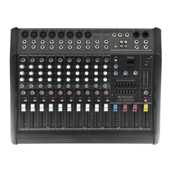
Powered live mixer
1
2
3
MIC
MIC
MIC
LINE
LINE
LINE
INSERT
INSERT
INSERT
1
2
3
-10
-10
-10
+4
+4
+4
GAIN
GAIN
0
0
0
HIGH
HIGH
HIGH
12 kHz
12 kHz
12 kHz
-15
+15
-15
+15
-15
+15
0
0
0
MID
MID
MID
2.5 kHz
2.5 kHz
2.5 kHz
-15
+15
-15
+15
-15
+15
0
0
0
LOW
LOW
LOW
80 Hz
80 Hz
80 Hz
-15
+15
-15
+15
-15
+15
0
0
0
AUX /
AUX /
AUX /
EFF
EFF
EFF
-
-
-
+15
+15
+15
PAN
PAN
L
R
L
R
L
R
L-R
L-R
L-R
G 1-2
G 1-2
G 1-2
PEAK
PEAK
PEAK
10
+dB
10
+dB
10
5
5
5
0
0
0
5
5
5
10
10
10
20
20
20
30
30
30
40
40
40
50
50
50
60
60
60
1
2
3
Für weiteren Gebrauch aufbewahren!
Keep this manual for future needs!
BEDIENUNGSANLEITUNG
USER'S MANUAL
LS-1222A
4
5
6
MIC
MIC
MIC
LINE
LINE
LINE
INSERT
INSERT
INSERT
4
5
6
-10
-10
-10
+4
+4
+4
GAIN
GAIN
GAIN
GAIN
0
0
0
HIGH
HIGH
HIGH
12 kHz
12 kHz
12 kHz
-15
+15
-15
+15
-15
+15
0
0
0
MID
MID
MID
2.5 kHz
2.5 kHz
2.5 kHz
-15
+15
-15
+15
-15
+15
0
0
0
LOW
LOW
LOW
80 Hz
80 Hz
80 Hz
-15
+15
-15
+15
-15
+15
0
0
0
AUX /
AUX /
AUX /
EFF
EFF
EFF
-
-
-
-
+15
+15
+15
PAN
PAN
PAN
PAN
L
R
L
R
L
R
L-R
L-R
L-R
G 1-2
G 1-2
G 1-2
PEAK
PEAK
PEAK
+dB
10
+dB
10
+dB
10
+dB
5
5
5
0
0
0
5
5
5
10
10
10
20
20
20
30
30
30
40
40
40
50
50
50
60
60
60
4
5
6
7
8
9-10
STEREO STEREO
MIC
MIC
L/MONO
LINE
LINE
R
INSERT
INSERT
7
8
9-10
-10
-10
-10
+4
+4
+4
+4
GAIN
GAIN
GAIN
0
0
0
HIGH
HIGH
HIGH
12 kHz
12 kHz
12 kHz
-15
+15
-15
+15
-15
+15
-15
0
0
0
MID
MID
MID
2.5 kHz
2.5 kHz
2.5 kHz
-15
+15
-15
+15
-15
+15
-15
0
0
0
LOW
LOW
LOW
80 Hz
80 Hz
80 Hz
-15
+15
-15
+15
-15
+15
-15
0
0
0
AUX /
AUX /
AUX /
EFF
EFF
EFF
-
-
-
-
+15
+15
+15
PAN
BAL
PAN
L
R
L
R
L
R
L-R
L-R
L-R
G 1-2
G 1-2
G 1-2
PEAK
PEAK
PEAK
10
+dB
10
+dB
10
+dB
5
5
5
0
0
0
5
5
5
10
10
10
20
20
20
30
30
30
40
40
40
50
50
50
60
60
60
7
8
9-10
11-12
AUX
PHONES
SEND
RETURN
L/MONO
L
L
TAPE ON
R
R
R
TAPE IN
TAPE OUT
TAPE
11-12
ECHO
DIGITAL EFFECT PROCESSING
-10
SEND / EFF
100 ms
GAIN
75 ms
AUX SEND
0
0
50 ms
25 ms
HIGH
12 kHz
0 ms
-
+15
+15
EFF LEVEL
AUX RETURN
0
0
0
MID
2.5 kHz
-
+15
-
+15
+15
0
LOW
80 Hz
GRAPHIC EQUALIZER
+15
0
+12
AUX /
EFF
0
+15
BAL
-12
63 Hz
150 Hz
400 Hz
1 kHz
2.5 kHz 6.4 kHz
L
R
L-R
LS-1222A
G 1-2
EFFECT
MAIN LEFT
MAIN RIGHT
PEAK
10
+dB
10
+dB
10
+dB
5
5
5
0
0
0
5
5
5
10
10
10
20
20
20
30
30
30
40
40
40
50
50
50
60
60
60
11-12
EFFECT
MAIN LEFT
MAIN RIGHT
Nachdruck verboten!
Reproduction prohibited!
MAIN LEFT
MAIN RIGHT
G 1
G 2
GROUP OUT
POWER
125 ms
+48V
150 ms
175 ms
200 ms
FEEDBACK
0
+10
+7
+4
-
+15
+2
0
-2
-4
-7
+12
-10
-20
0
HEADPHONES LEVEL
0
-12
15 kHz
-
+15
L-R /
G 1-2
G 1-2
to
L-R
GROUP 1-2
10
+dB
10
+dB
5
5
0
0
5
5
10
10
20
20
30
30
40
40
50
50
60
60
GROUP 1-2
©
Copyright
Advertisement
Table of Contents

Related Manuals for Omnitronic LS-1222A


Summary of Contents for Omnitronic LS-1222A
- Page 1 BEDIENUNGSANLEITUNG USER'S MANUAL LS-1222A Powered live mixer 9-10 11-12 PHONES MAIN LEFT MAIN RIGHT SEND RETURN STEREO STEREO L/MONO L/MONO TAPE ON LINE LINE LINE LINE LINE LINE LINE LINE TAPE IN TAPE OUT INSERT INSERT INSERT INSERT INSERT INSERT...
-
Page 2: Table Of Contents
8.1 Replacing the fuse ..........................31 9. TECHNICAL SPECIFICATIONS......................... 31 BLOCK DIAGRAM............................33 Das neueste Update dieser Bedienungsanleitung finden Sie im Internet unter: You can find the latest update of this user manual in the Internet under: www.omnitronic.com 2/32 10060200_V_1_1.DOC... -
Page 3: Einführung
- sich die letzte Version der Anleitung im Internet herunter laden 1. EINFÜHRUNG Wir freuen uns, dass Sie sich für ein OMNITRONIC LS-1222A entschieden haben. Wenn Sie nachfolgende Hinweise beachten, sind wir sicher, dass Sie lange Zeit Freude an Ihrem Kauf haben werden. - Page 4 Bitte überprüfen Sie vor der ersten Inbetriebnahme, ob kein offensichtlicher Transportschaden vorliegt. Sollten Sie Schäden an der Netzleitung oder am Gehäuse entdecken, nehmen Sie das Gerät nicht in Betrieb und setzen sich bitte mit Ihrem Fachhändler in Verbindung. Der Aufbau entspricht der Schutzklasse I. Der Netzstecker darf nur an eine Schutzkontakt-Steckdose angeschlossen werden, deren Spannung und Frequenz mit dem Typenschild des Gerätes genau übereinstimmt.
-
Page 5: Bestimmungsgemäße Verwendung
Schließen Sie die Ein- oder Ausgänge niemals an eine Stromquelle an (Batterie, o.ä.). Vermeiden Sie unter allen Umständen, dass Ausgang mit Ausgang verbunden wird! Bevor das Gerät eingeschaltet wird, müssen alle Fader und Lautstärkeregler auf "0" bzw. auf minimum gestellt werden. ACHTUNG: Endstufen immer zuletzt einschalten und zuerst ausschalten! Kinder und Laien vom Gerät fern halten! GESUNDHEITSRISIKO! -
Page 6: Features
Nehmen Sie das Gerät erst in Betrieb, nachdem Sie sich mit seinen Funktionen vertraut gemacht haben. Lassen Sie das Gerät nicht von Personen bedienen, die sich nicht mit dem Gerät auskennen. Wenn Geräte nicht mehr korrekt funktionieren, ist das meist das Ergebnis von unsachgemäßer Bedienung! Reinigen Sie das Gerät niemals mit Lösungsmitteln oder scharfen Reinigungsmitteln, sondern verwenden Sie ein weiches und angefeuchtetes Tuch. - Page 7 STEREO STEREO L/MONO L/MONO LINE INSERT Bei den Mono-Eingangskanälen werden die Mikrofonsignale über die XLR-Buchsen angeschlossen, die Line-Signale über die Klinkenbuchsen. Bitte beachten Sie: An einen Monokanal darf immer nur eine Signalart angeschlossen werden – entweder Mic oder Line. Einen Stereo-Kanal können Sie auch mono betreiben, indem Sie nur die linke Eingangsbuchse belegen. Hier können Sie Kondensatormikrofone oder dynamische Mikrofone über eine symmetrische XLR-Leitung anschließen.
-
Page 8: Inserts
Belegung Klinkenstecker: Symmetrischer 6,35 mm Unsymmetrischer 6,35 mm Mono-Klinkenstecker tereo -Klinkenstecker Tip = Tip = Signal (+) Plus-Phase (+) Ring = Minus-Phase (-) Sleeve = Masse / Schirm Sleeve = Masse / Schirm Ring Sleeve Sleeve Zugentlastung Zugentlastung Um einen Stereo-Klinkenstecker unsymme- trisch an zu schließen, müssen Ring und Sleeve gebrückt werden. -
Page 9: Anschlüsse
Das Ausgangssignal des Mischpults wird über ein Y-Kabel mit dem Eingang (Tip&Sleeve) und Ausgang (Ring&Sleeve) des Effektgeräts verbunden. Die INSERT-Buchsen können auch als Direktausgänge für die MIC-Kanäle verwendet werden. Direktaus- gänge werden benötigt, wenn Sie z. B. während eines Konzerts Mehrspuraufnahmen machen möchten. Jede Signalquelle kann zum späteren Abmischen auf eine eigene Spur aufgenommen werden. -
Page 10: Gerätebeschreibung
5. GERÄTEBESCHREIBUNG 5.1 Kanalzug GAIN Mit dem Gain-Regler können Sie die Eingangssignale verstärken bzw. abschwächen. Der Regelbereich liegt zwischen 10 und 60 dB für die Mikrofonsignale und +10 bis –40 dBu für die Line-Signale. Die gebräuchlichsten Arbeitspegel –10 dBV und +4 dBu sind GAIN auf dem Skalenkranz hervorgehoben. -
Page 11: Master-Sektion
2.5 kHz 6.4 kHz 15 kHz Angeschlossene dynamische Mikrofone können betrieben werden, wenn Sie L-R / G 1-2 symmetrisch beschaltet sind. LS-1222A G 1-2 Zweifelsfall wenden Sie sich bitte an den Mikrofonhersteller. EFFECT MAIN LEFT MAIN RIGHT GROUP 1-2 Bitte... -
Page 12: Effekt-Sektion
Fuse 115 V: T 12 A, 250 V www.omnitronic.com SPEAKER POWER OMNITRONIC SHOWEQUIPMENT GmbH, GERMANY RIGHT LEFT CAUTION Read user manual before use. Keep away from moisture! Disconnect from mains before changing fuse. Replace the fuse only with the same type and rating. -
Page 13: Bedienung
SPEAKER-AUSGANGSBUCHSEN Zum Boxenanschluss für Kanal 1 und 2. AC INPUT-BUCHSE Stecken Sie hier die Netzleitung ein. SICHERUNGSHALTER Ersetzen Sie die Sicherung nur bei ausgestecktem Gerät und nur durch eine gleichwertige Sicherung. SPANNUNGSWAHLSCHALTER Achten Sie auf die richtige Einstellung. LÜFTER 6. BEDIENUNG Bitte achten Sie während des Betriebes darauf, dass die Lautsprecherboxen stets angenehm klingen. -
Page 14: Routing
Lärmbereich vor. Somit hat der Arbeitgeber Warnschilder aufzustellen und Gehörschutzmittel bereitzustellen. Die Arbeitnehmer haben diese zu benutzen. Bitte beachten Sie: OMNITRONIC haftet nicht für Schäden, die durch unsachgemäße Installation und übermäßige Lautstärken verursacht werden! 14/32... -
Page 15: Kleine Hörkunde
7.1 Kleine Hörkunde Immer mehr junge Menschen leiden unter einem Hörverlust von 25 Dezibel und mehr, überwiegend hervorgerufen durch laute Musik von tragbaren Kassetten- und CD-Abspielgeräten oder in der Diskothek. Wer Musik über Beschallungsanlagen wiedergibt, sollte wissen, welchen Schallpegeln er sein Gehör und das des Publikums aussetzt. -
Page 16: Reinigung Und Wartung
8. REINIGUNG UND WARTUNG Der Unternehmer hat dafür zu sorgen, dass sicherheitstechnische und maschinentechnische Einrichtungen mindestens alle vier Jahre durch einen Sachverständigen im Umfang der Abnahmeprüfung geprüft werden. Der Unternehmer hat dafür zu sorgen, dass sicherheitstechnische und maschinentechnische Einrichtungen mindestens einmal jährlich durch einen Sachkundigen geprüft werden. Dabei muss unter anderem auf folgende Punkte besonders geachtet werden: 1) Alle Schrauben, mit denen das Gerät oder Geräteteile montiert sind, müssen fest sitzen und dürfen nicht korrodiert sein. -
Page 17: Technische Daten
9. TECHNISCHE DATEN Spannungsversorgung: 115/230 V AC, 50/60 Hz ~ Gesamtanschlusswert: 800 W Eingänge: 8 mono XLR oder Klinke symmetrisch 8 Inserts Klinke 2 stereo Klinke symmetrisch 1 Aux-Return Klinke symmetrisch Tape In Cinch Ausgänge: 1 Main Mix Out XLR oder Klinke symmetrisch 1 Headphones Klinke symmetrisch 1 Aux-Send... -
Page 18: Introduction
- download the latest version of the user manual from the Internet 1. INTRODUCTION Thank you for having chosen an OMNITRONIC LS-1222A. If you follow the instructions given in this manual, we are sure that you will enjoy this device for a long period of time. - Page 19 If the device has been exposed to drastic temperature fluctuation (e.g. after transportation), do not switch it on immediately. The arising condensation water might damage your device. Leave the device switched off until it has reached room temperature. Please make sure that there are no obvious transport damages. Should you notice any damages on the A/C connection cable or on the casing, do not take the device into operation and immediately consult your local dealer.
-
Page 20: Operating Determinations
Never connect output to output. Before the device is switched on all faders and volume controls have to be set to "0" or "min" position. CAUTION: Turn the amplifier on last and off first! Please note that damages caused by manual modifications on the device or unauthorized operation by unqualified persons are not subject to warranty. -
Page 21: Features
Never use solvents or aggressive detergents in order to clean the device! Rather use a soft and damp cloth. Please use the original packaging if the device is to be transported. Never remove the serial barcode from the device as this would make the guarantee void. Please consider that unauthorized modifications on the speaker-system are forbidden due to safety reasons! If this device will be operated in any way different to the one described in this manual, the product may suffer damages and the guarantee becomes void. - Page 22 STEREO STEREO L/MONO L/MONO LINE INSERT At the mono input channels, the microphone signals are connected via the XLR-sockets, the line-signals via the jack sockets. Please note: you must only connect one kind of signal to a mono channel – either mic or line. You can also run a stereo channel in mono when you only connect the left input socket.
-
Page 23: Inserts
Occupation jack plug: Balanced use of Unbalanced use of mono 1/4" jack plugs stereo 1/4" jack plugs Tip = Tip = Signal (+) hot (+) Ring = cold (-) Sleeve = Ground / Shield Sleeve = Ground / Shield Ring Sleeve Sleeve Strain relief clamp... -
Page 24: Connections
4.3 Connections PHONES SEND RETURN AUX SEND/RETURN Connect your effectors or monitor system/zone system with the AUX SEND-sockets. AUX is POST-fader and can be used for your effectors. You can adjust the signal level for the AUX SEND-socket via the AUX SEND-control. -
Page 25: Description Of The Device
5. DESCRIPTION OF THE DEVICE 5.1 Channel-section GAIN With the GAIN-control, you can set the level of the input signal. The control range is between 10 and 60 dB for the microphone signals and +10 to –40 dBu for the line GAIN signals. -
Page 26: Master-Section
1 kHz 2.5 kHz 6.4 kHz 15 kHz L-R / Please note: the phantom power must G 1-2 only be activated if all microphones are LS-1222A G 1-2 connected and all output controls are set minimum position. During EFFECT MAIN LEFT... -
Page 27: Effect-Section
Fuse 115 V: T 12 A, 250 V www.omnitronic.com SPEAKER POWER OMNITRONIC SHOWEQUIPMENT GmbH, GERMANY RIGHT LEFT CAUTION Read user manual before use. Keep away from moisture! Disconnect from mains before changing fuse. Replace the fuse only with the same type and rating. -
Page 28: Operation
AC INPUT SOCKET Used to plug the power cord in. FUSEHOLDER Only replace the fuse when the device is disconnected from mains. Only use fuses of the same rating and power. AC VOLTAGE-SELECTOR Make sure that the selector is properly set. VENTILATION FAN 6. -
Page 29: Effect Generator
This is why the entrepreneur has to set up warning signs and provide hearing protectors. The staff has to use these. Please note: OMNITRONIC cannot be made liable for damages caused by incorrect installations and excessive noise levels! 7.1 Information on hearing loss More and more young people suffer from hearing loss of 25 dezibel or more, mainly caused by loud music from protable cassette recorders and CD-players or discotheques. -
Page 30: Cleaning And Maintenance
Overview on the different noise levels 10 dB Heartbeat 20 - 30 dB Whisper 40 dB Average home 50 dB Light traffic 60 dB Normal conversation 70 dB Vacuum cleaner 80 dB Heavy traffic or telephone ringing 90 dB Pneumatic drill 100 dB Power mower 120 dB... -
Page 31: Replacing The Fuse
There are no servicable parts inside the device except for the fuse. Maintenance and service operations are only to be carried out by authorized dealers. 8.1 Replacing the fuse If the fine-wire fuse of the device fuses, only replace the fuse by a fuse of same type and rating. Before replacing the fuse, unplug mains lead. -
Page 32: Block Diagram
Block diagram 32/32 10060200_V_1_1.DOC...
Need help?
Do you have a question about the LS-1222A and is the answer not in the manual?
Questions and answers