
Related Manuals for Amprobe PM-60


Summary of Contents for Amprobe PM-60
- Page 1 PM-60 Pocket Meter Users Manual • Mode d’emploi • Bedienungshandbuch • Manual d’Uso • Manual de uso...
- Page 3 PM-60 Pocket Meter Users Manual ©2009 Amprobe Test Tools. All rights reserved. Printed in China...
- Page 4 “Where to Buy” section on www.amprobe.com for a list of distributors near you. Additionally, in the United States and Canada In-Warranty repair and replacement units can also be sent to a Amprobe® Test Tools Service Center (see next page for address).
- Page 5 Non-Warranty Repairs and Replacement – US and Canada Non-warranty repairs in the United States and Canada should be sent to a Amprobe® Test Tools Service Center. Call Amprobe® Test Tools or inquire at your point of purchase for current repair and replacement rates.
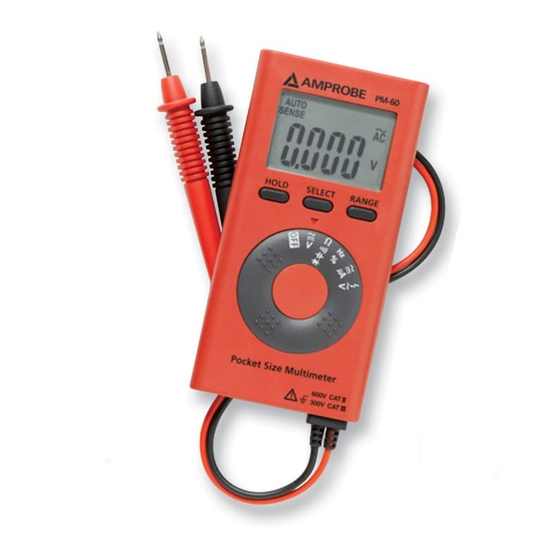
- Page 6 PM-60 Pocket Meter 1). LCD Display 2). Hold function key 3). Function selection key 4). Range key 5). Function Selector 6). Test Leads...
-
Page 7: Table Of Contents
CONTENTS SYMBOLS ................2 UNPACKING AND INSPECTION ........3 INTRODUCTION ..............3 OPERATION ............... 4 SPECIFICATION ..............8 MAINTENACE ..............13 TROUBLE SHOOTING ............13 Battery Replacement ........... 14... -
Page 8: Symbols
SYMBOLS Warning! Dangerous Voltage (Risk of electric shock). Caution ! Refer to the user’s manual before � using this Meter. Double Insulation or Reinforced insulation Alternating Current (AC). Direct Current (DC). Low battery indicator Ground (maximum permitted voltage between terminal and ground). Please remove all the test leads before preforming maintenance, cleaning, battery �... -
Page 9: Unpacking And Inspection
INTRODUCTION This meter PM-60 can be measured voltage, resistance, frequency, capacitance, diode, current (uA) and continuity; It is an electronic measuring instrument that combines several measurement functions in one unit. -
Page 10: Operation
OPERATION Auto Power Off Display Hold The internal sounder will operate continuously with LCD display flashing in two situations in the Data Hold mode: 1. The Meter measure a signal different from the LCD reading. 2. The measured signal is the same unit as the LCD reading and is larger 50 counts than the LCD reading. - Page 11 Auto Range / Manual Range Selecting Function...
- Page 12 Resistor / Capacitor / Continuity / Diode • For better measurement accuracy of small value capacitance, subtract the residual capacitance of the Meter and leads from measurement. • Under diode mode, LCD displays “bad” when measuring a diode conducted at forward and reverse bias.
- Page 13 AC V / DC / Hz / Duty � CAUTION When connecting the test leads to the circuit or device, connect the black lead first, then connect the red lead ; when removing the test leads, remove the red lead first, then remove the black lead.
-
Page 14: Specification
• If no indication, voltage could still be present. • Using only red test probe to work as mains voltage indicator. AC A / DC A SPECIFICATION General Specifications LCD display digits: 4000 counts digit large scale LCD readout. Measuring rate: 3 times / sec. Polarity Indication:Automatic, positive implied, Overrange display: “OL”... -
Page 15: Electrical Specifications
Storage temperature: -20 to +60°C (-4°F to 140°F), 0 to 80% RH (batteries not fitted). Temperature coefficient: Add 0.2 x (Specified accuracy) / °C, < 18°C (64.4°F), > 28°C (82.4°F). Shock vibration: Sinusoidal vibration per MIL-T-28800E (5 ~ 55 Hz, 3g/0.007lb maximum). Drop Protection: 4 feet drop to hardwood on concrete floor. - Page 16 Function Ranges Resolution Accuracy 400.0mV 0.1mV ± (1.5%+ 5 D) 4.000V 0.001V 40.00V 0.01V ± (0.9%+ 5 D) 400.0V 0.1V 600V Frequency Response: 50 ~ 500Hz AC Conversion Type: AC Coupled Average Sensing, RMS Indication. Input Impedance: 10Me, <100pF. Overload protection: 600V rms. Function Ranges Resolution...
- Page 17 CONTINUITY CHECK Continuity Threshold: Approx. <50e Continuity Indicator: 2.7 KHz Tone Buzzer. Input Protection: 600V rms.. Function Ranges Resolution Accuracy 40.00nF 0.01nF ± (5%+ 0.4nF) 400.0nF 0.1nF 4.000µF 0.001µF ± (2.9%+ 5D) 40.00µF 0.01µF 400.0µF 0.1µF Measuring Time: <30sec. (400.0µF range), <10sec.
- Page 18 Square Wave (5 Hz ~ 1KHz) Sensitivity: 1.5Vp-p Overload protection: 600V rms. Function Ranges Resolution Accuracy 400.0µA 0.1µA ± (1.5%+ 5 D) 4.000mA 0.001mA Frequency Response: 50 ~ 500Hz AC Conversion Type: AC Coupled Average Sensing, RMS Indication. Input Impedance: Approx. 3Ke Overload protection: 600V rms.
-
Page 19: Maintenace
MAINTENACE If there appears to be a malfunction during the operation of the following steps should be performed in order meter, the to isolate the cause of the problem. 1. Check the battery. Replace the battery immediately when the “N” symbol appears on the LCD. -
Page 20: Battery Replacement
gaps should then be replaced by qualified technician. Refer the LIMITED WARRANTY section for obtaining warranty or repairing service. Battery Replacement Refer to the following figure to replace the batteries:...
Need help?
Do you have a question about the PM-60 and is the answer not in the manual?
Questions and answers