
Subscribe to Our Youtube Channel
Related Manuals for Amprobe PXP-A


Summary of Contents for Amprobe PXP-A
- Page 1 5XP-A 15XP-A 35XP-A Compact Digital Multimeters Users Manual 99 Washington Street Melrose, MA 02176 Fax 781-665-0780 TestEquipmentDepot.com...
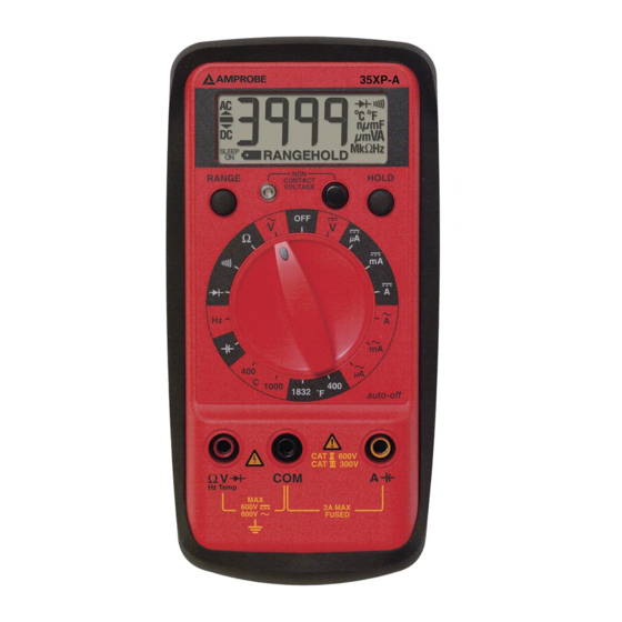
- Page 2 35XP-A RANGE HOLD CONTACT VOLTAGE °C 1000 1832 °F auto-off 1000V 600V 300V Hz Temp 1000V 2A MAX 750V FUSED 35XP-A...
-
Page 3: Table Of Contents
XP Series Digital Multimeters Contents Safety Information ....................2 Symbols Used in this Manual ................3 Making Measurements..................3 Verify Instrument Operation................3 Range Selection ....................3 Correcting an Overload (0o or -0o) Indication W..........3 Measuring DC Voltage See Figure .............3 Measuring AC Voltage See Figure .............4 Preparing for Current Measurements...............4 Measuring DC Current... -
Page 4: Safety Information
35XP-A 5XP-A 15XP-A 5XP-A 15XP-A 35XP-A MIN MAX HOLD RANGE HOLD RANGE HOLD CONTACT CONTACT CONTACT VOLTAGE VOLTAGE VOLTAGE 1000 200k 200m ˚C 1000 1.5V 9V 1832 auto-off ˚F auto-off BATT CAT 1000V CAT 1000V CAT 1000V 600V 600V 600V 300V 300V 300V... -
Page 5: Symbols Used In This Manual
Symbols Used in this Manual Battery Refer to the manual Double insulated Dangerous Voltage Direct Current Earth Ground Alternating Current Audible tone Fuse Canadian Standards Association Complies with EU Non-contact Voltage directives Making Measurements Verify Instrument Operation Before attempting to make a measurement, verify that the instrument is operational and the battery is good. -
Page 6: Measuring Ac Voltage
Measuring AC Voltage See Figure 1. Set the Function Switch to V. 2. Select the desired RANGE. The default AC voltage range is 2 V on the 15XP-A and 4 V on the 35XP-A. 3. Connect the test leads: Red to E, Black to COM. 4. -
Page 7: Measuring Resistance
Measuring Resistance See Figure Ω 1. Set the Function Switch to 2. Select the desired RANGE (5XP-A, 15XP-A). 3. Connect the test leads: Red to E, Black to COM. 4. Turn off power to the circuit being measured. Never measure resistance across a voltage source or on a powered circuit. -
Page 8: Measuring Temperature (35Xp-A Only)
Measuring Temperature (35XP-A only) See Figure 1. Set the function switch to appropriate °C or °F range. 2. Connect the K-type thermocouple to a TEMP adapter (XR-TA). Match the polarity of the adapter to the polarity of the thermocouple. 3. Connect the TEMP adapter to the E and COM inputs. Note: The 35XP-A is compatible with all K-type thermocouples. -
Page 9: Testing Logic Levels (15Xp-A Only) See Figure -13
Testing Logic Levels (15XP-A only) See Figure -13- The 15XP-A tests logic levels for TTL logic. The meter displays 0o plus a ∧ for a high-level (true) condition. The meter beeps and displays an 0o and a ∨ for a low-level (false) condition. -
Page 10: Product Maintenance
3. Remove and replace the 2 A fuse (15XP-A or 35XP-A) or 0.315 fuse (5XP-A). 4. Reassemble the meter. Fuse: Fast Blow 2 A/1000 V, minimum interrupt rating 30 kA (6 x 32 mm) (Amprobe FP200). ® Fast Blow 0.315 A/1000 V minimum interrupt rating 30 kA (6.3 x 32 mm) -
Page 11: Repair
AC CURRENT (45 Hz to 500 Hz) DC CURRENT Ranges: 200 µA, 2 mA, 20 mA, 200 mA, Ranges: 200 µA, 2000 µA, 20 mA, 200 mA, 2 A ± (2.0 % rdg + 5 dgts) Accuracy: ±(1.0 % rdg + 2 dgts) on RESISTANCE 200 µA to 200 mA ranges: ±(2.0 % rdg Ranges: 200 Ω, 2 kΩ, 20 kΩ, 200 kΩ,... -
Page 12: Specifications
TEMPERATURE 35XP-A Electrical Ranges: -20°C to 1000°C, -4°F to 1832°F Specifications Accuracy: ± (2.0 % rdg +4°C) -20°C to (at 23°C ± 5°C, < 75 % R.H.) 10°C DC VOLTS ± (1.0 % rdg + 3°C)10°C to 200°C Ranges: 400 mV, 4 V, 40 V, 400 V, ±... - Page 13 35XP-A RANGE HOLD CONTACT VOLTAGE ˚C 1000 1832 ˚F auto-off CAT 1000V 600V 300V Hz Temp 1000V 2A MAX 750V FUSED 35XP-A RANGE HOLD CONTACT VOLTAGE ˚C 1000 1832 ˚F auto-off CAT 1000V 600V 300V Hz Temp 1000V 2A MAX 750V FUSED...
- Page 14 35XP-A RANGE HOLD CONTACT VOLTAGE ˚C 1000 1832 ˚F auto-off CAT 1000V 600V 300V Hz Temp 1000V 2A MAX 750V FUSED 35XP-A RANGE HOLD CONTACT VOLTAGE ˚C 1000 1832 ˚F auto-off CAT 1000V 600V 300V Hz Temp 1000V 2A MAX 750V FUSED...
- Page 15 35XP-A RANGE HOLD CONTACT VOLTAGE ˚C 1000 1832 ˚F auto-off CAT 1000V 600V 300V Hz Temp 1000V 2A MAX 750V FUSED 35XP-A RANGE HOLD CONTACT VOLTAGE ˚C 1000 1832 ˚F auto-off CAT 1000V 600V 300V Hz Temp 1000V 2A MAX 750V FUSED...
- Page 16 35XP-A RANGE HOLD CONTACT VOLTAGE ˚C 1000 1832 ˚F auto-off CAT 1000V 600V 300V Hz Temp 1000V 2A MAX 750V FUSED 35XP-A RANGE HOLD CONTACT VOLTAGE ˚C 1000 1832 ˚F auto-off CAT 1000V 600V 300V Hz Temp 1000V 2A MAX 750V FUSED...
- Page 17 35XP-A RANGE HOLD CONTACT VOLTAGE ˚C 1000 1832 ˚F auto-off CAT 1000V 600V 300V Hz Temp 1000V 2A MAX 750V FUSED 35XP-A RANGE HOLD CONTACT VOLTAGE ˚C 1000 1832 ˚F auto-off CAT 1000V 600V 300V Hz Temp 1000V 2A MAX 750V FUSED...
- Page 18 35XP-A RANGE HOLD ˚C 1000 1832 ˚F auto-off CAT 1000V 600V 300V Hz Temp 1000V 2A MAX 750V FUSED BATT 5XP-A MIN MAX HOLD CONTACT VOLTAGE 1000 200k 200m 1.5V 9V BATT CAT 1000V 600V 300V BATT 9V BATT 1.5V 1000V 200mA MAX 750V...
- Page 19 15XP-A (15XP-A/35XP-A) (5XP-A)
Need help?
Do you have a question about the PXP-A and is the answer not in the manual?
Questions and answers