
Subscribe to Our Youtube Channel
Related Manuals for Amprobe Hexagon 60


Summary of Contents for Amprobe Hexagon 60
-
Page 1: Digital Multimeter
Hexagon 60 Digital Multimeter Users Manual 04/2013, RevA ©2013 Beha-Amprobe. All rights reserved. Printed in China... - Page 2 Limited Warranty and Limitation of Liability Your Amprobe product will be free from defects in material and workmanship for one year from the date of purchase, unless local laws require otherwise. This warranty does not cover fuses, disposable batteries or damage from accident, neglect, misuse, alteration, contamination, or abnormal conditions of operation or handling.
- Page 3 Non-Warranty Repairs and Replacement – US and Canada Non-warranty repairs in the United States and Canada should be sent to an Amprobe® Service Center. Call Amprobe® or inquire at your point of purchase for current repair and replacement rates. In USA:...
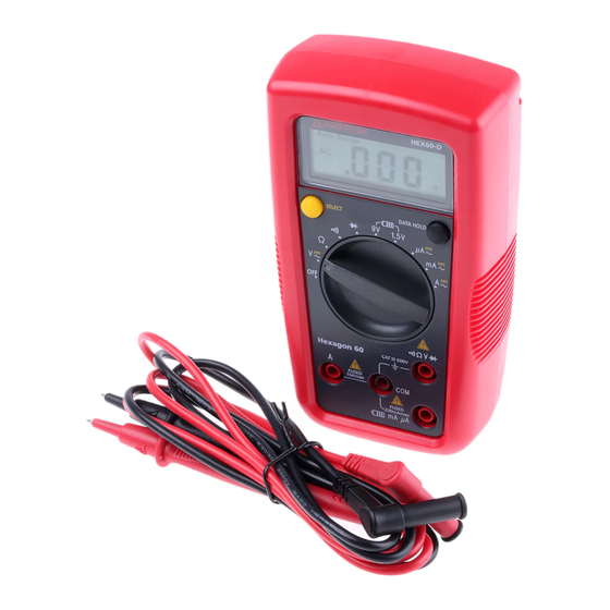
- Page 4 Hexagon 60 Digital Multimeter LCD Display DATA HOLD Button SELECT Button Rotary Switch Input Terminal for voltage, diode, resistance and continuity measurement Input Terminal for battery test and AC/DC mA or μA measurement Input Terminal for AC/DC A measurement to10A...
- Page 5 Screen Display The Meter selects the range with best resolution Direct Current Alternate Current Negative reading Data hold Diode test Continuity test Measurement units for resistance test Measurement units for voltage test Measurement units for current test Low battery indicator Battery Test...
-
Page 6: Table Of Contents
CONTENTS SYMBOLS ................2 SAFETY INFORMATION ............2 UNPACKING AND INSPECTION .......... 4 FEATURES ................4 MAKING MEASUREMENT ..........5 Rotary Switch Positions ..........5 SELECT Button ..............6 DATA HOLD Button ............6 Auto Power OFF ............. 6 Measuring AC and DC Voltage ........6 Measuring Resistance ............ -
Page 7: Symbols
SYMBOLS Caution ! Risk of electric shock. � Caution! Refer to the explanation in this Manual Alternating Current (AC) Direct Current (DC) The equipment is protected by double insulation or reinforced insulation Earth (Ground) Audible tone Battery � Complies with European Directives Conforms to relevant Australian standards �... - Page 8 CENELEC Directives The instruments conform to CENELEC Low-voltage directive 2006/95/EC and Electromagnetic compatibility directive 2004/108/EC Warning: Read Before Using X� • To avoid possible electrical shock or personal injury, follow these instructions and use the Meter only as specified in this manual. • Do not use the Meter or test leads if they appear damaged, or if the Meter is not operating properly. If in doubt, have the Meter serviced. • Always use the proper function and range for measurements. • Before rotating the function range selection switch, disconnect test probe from circuit under test. • Verify the Meter’s operation by measuring on a known voltage source.
-
Page 9: Unpacking And Inspection
CAT III 600V rated product. Check for voltage in electrical sockets, extension cords, batteries and other electrical circuits. Let the power of a professional Amprobe multimeter keep you safe and help you solve all your electrical challenges. • Measurements: Voltage up to 600V AC/DC, AC/DC Current and Resistance • Audible continuity... -
Page 10: Making Measurement
MAKING MEASUREMENT X� 1. Use the proper function and range for measurements. 2. To avoid possible electrical shock, personal injury or damages to the Meter, disconnect circuit power and discharge all high-voltage capacitors before testing resistance and diode. 3. Connecting test leads: • Connect the common (COM) test lead to the circuit before connecting the live lead. -
Page 11: Select Button
Press to select altemate measurement SELECT functions on the rotary switch. Button DATA Display freezes present reading HOLD SELECT Button Press the yellow SELECT button to select alternate measurement functions on the rotary switch. DATA HOLD Button Press DATA HOLD button to freeze present reading on display. -
Page 12: Measuring Resistance
Measuring Resistance X� Disconnect circuit power and discharge all high-voltage capacitors before testing resistance. Note: On a higher resistance measurement (>1Me), the measurement may take a few seconds to get stable reading. Measuring Continuity X� Disconnect circuit power and discharge all high- voltage capacitors before testing continuity. -
Page 13: Measuring Diode
Measuring Diode X� Disconnect circuit power and discharge all high- voltage capacitors before testing diode. Battery Test X� Applying a voltage source or incorrect battery type under battery test may cause personal Injury or damage to the Meter. Battery 1.5V range is for dry battery not exceeding 2Vdc. The resistance load is around 30Ω. -
Page 14: Measuring Ac And Dc Current
Measuring AC and DC Current Press SELECT button for switching to DC current measurement function. X� To avoid personal injury or damage to the Meter: 1. Do not attempt to make an in-circuit current measurement when the open-circuit potential to earth ground exceeding 600 V. -
Page 15: Specification
SPECIFICATION Ambient temperature: 23°C ±5°C (73.4°F ±9°F) Relative temperature: ≤75% Accuracy: ±(% of reading + digits) Maximum voltage between input terminal and earth ground: AC 600Vrms or DC 600V � Fuse for mA μA input: 0.5A H 700V fast-fuse, 6.3x32mm �... - Page 16 1. DC Voltage Measurement Range Resolution Accuracy 200.0mV 0.1mV ±(0.8%+3dgt) 2.000V 20.00V 10mV ±(0.8%+1dgt) 200.0V 100mV 600V ±(1.0%+3dgt) Input impedance: around 10MΩ; (Input impedance > 3GΩ for DC 200mV range) Overload protection: 600VDC or AC rms 2. AC Voltage Measurement Range Resolution Accuracy...
- Page 17 200Ω range: Measured value = (Measured display value) – (Short-circuiting value of probe) Open circuit voltage: around 0.5V Overload protection: 600V : Continuity G : Diode measurement Range Resolution Accuracy Open circuit voltage is around 0.5V. Resistance >150Ω, buzzer will not sound.
- Page 18 6. DC Current Measurement Range Resolution Accuracy 200.0μA 0.1μA μA 2000μA 1μA ±(1.0%+2dgt) 20.00mA 10μA 200.0mA 0.1mA 2.000A ±(1.2%+3dgt) 10.00A 10mA Overload protection: � mA /μA input: F1 fuse, 0.5A H 700V fast-fuse, 6.3x32mm 10 A input: F2 fuse, 10A H 600V fast-fuse, 6x25mm 7.
-
Page 19: Maintenance And Repair
MAINTENANCE AND REPAIR If the Meter fails to operate, check battery, test leads, etc., and replace as necessary. Double check the followings: 1. Replace the fuse or battery if the meter does not work. 2. Review the operating instructions for possible mistakes in operating procedure. -
Page 20: Battery And Fuse Replacement
5. Put the battery cover back and re-fasten the screw. Battery: 1.5V Alkaline Batteries (AAA) or equivalent Replacing FUSE follow below steps: 1. Disconnect the test lead probe from measuring circuit. 2. Turn the Meter to OFF position and remove the holster. - Page 22 Beha-Amprobe In den Engematten 14 79286 Glottertal, Germany Tel.: +49 (0) 7684 8009 - 0 Fax.: +49 (0) 7684 8009 - 410 www.beha-amprobe.de Please Recycle...
Need help?
Do you have a question about the Hexagon 60 and is the answer not in the manual?
Questions and answers