
Related Manuals for Moog DS2110


Summary of Contents for Moog DS2110
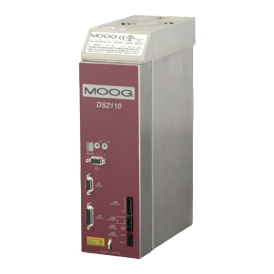
- Page 1 DS2110 DIGITAL CONTROLLER INSTALLATION & USER’S MANUAL Document No.: CDS7324 (formerly LSF-0819) Revision: A Date: May 2011 INDUSTRIAL CONTROLS DIVISION...
-
Page 2: Table Of Contents
3.8 24V Backup Connection ....................3-29 3.9 Internal/External Regeneration (Regen) Resistors – Configurations ......3-32 3.10 Motors – Installation ...................... 3-36 3.11 DS2110 Control Inputs and Outputs................3-49 3.12 Communication Interface Wiring and Configuration ..........3-54 3.13 Wiring Summary......................3-55 CHAPTER 4.0 GETTING STARTED .................... - Page 3 APPENDIX E – ANALOG I/O MEZZANINE CARD ................ E.1 Introduction........................E.2 Overview........................... E.3 Configurations ......................... E.4 Analog I/O......................... E.5 SSI Interface ........................E.6 Simulated Encoder/Resolver ..................E.7 PLC Master – DS2110 Slave Arrangement..............E.8 Noise Reduction ......................CDS7324 REV. A INSTALLATION & USER’S MANUAL...
- Page 4 APPENDIX G – ETHERNET MEZZANINE CARD................G.1 Introduction ........................G.2 Modes of Operation......................G.3 Changing IP Address for Ethernet Device ..............G.4 Changing Commands and Status Registers..............G.5 Allen-Bradley RSLogix Configuration with DS2110 ............. CDS7324 REV. A INSTALLATION & USER’S MANUAL...
- Page 5 CHAPTER 1.0 Overview 1.1 Introduction This section gives an overview of the available DS2110 models, ratings and general specifications. Detailed outlines of installation and wiring, functionality, user interfaces and other technical data are given in subsequent sections. CAUTION: Repairs or modifications to the product by anyone other than a Moog authorized repair facility may create unsafe operating conditions and will invalidate the product warranty.
- Page 6 CHAPTER 1.0 Overview 1.2 DS2110 Models The DS2110 family is available in twelve base models, which cover a range of output current ratings. DS2110 Base Model Amplifier Current Rating Code Size Continuous Maximum (Arms) Peak (A) (Arms) G362-x03 µA or A...
- Page 7 CHAPTER 1.0 Overview Page Intentionally Blank CDS7324 (FORMERLY LSF-0819) Rev. A INSTALLATION & USER’S MANUAL...
- Page 8 CHAPTER 1.0 Overview 1.3 Environmental Specifications DS2110 Electronics Maximum temperature Storage: -25 C to 55 C (Class 1K4) Transport: -25 C to 70 C (Class 2K3) Surrounding air 0 C to 40 C Relative humidity: 5 % to 85 %, non-condensing, 1 g/m3 to 25 g/m3, in accordance with...
- Page 9 CHAPTER 1.0 Overview 1.4 Design Standards The DS2110 is CE-Marked under the EU's Low Voltage Directive. It has been designed to allow easy compliance of customer's machines under the EU's EMC Directive (measures as directed in this manual have to be taken to ensure EMC compliance). It is designed to the UL508C standard. The size DS2110 units are UL recognized.
- Page 10 D.C. Bus Undervoltage Bridge Temperature Fault Amplifier Short Circuit Protection 24V Logic Backup Monitoring Voltage Discharge after A.C Bleed Resistors across high voltage section. Mains Removal Table 1.3 DS2110 Power Ratings CDS7324 (FORMERLY LSF-0819) Rev. A INSTALLATION & USER’S MANUAL...
- Page 11 Table 1.4 DS2110 Control Logic Backup Power Ratings An auxiliary 24V d.c. control logic backup supply is MANDATORY for the –x003 & -x006 variants of the DS2110 product family. The 24V Backup supply input is intended for use in the secondary of a Class 2 supply.
- Page 12 IGBT die temperature cannot increase above the device maximum rating. For the DS2110 D size, a simple thermal shutdown is implemented. These drives will report an overtemperature fault once the measured heatsink temperature exceeds the maximum rating of the drive.
-
Page 13: Chapter 1.0 Overview
CCW limit Switch See Section 5.9 Quick Stop See Section 5.9 Controlled Disable See Section 5.9 Table 1.6 DS2110 Digital Inputs Overview : Standard Configuration 1.6.2 Digital Outputs (J2B) • 3 Digital outputs, user configurable • All outputs are Optically Isolated. - Page 14 Relay output, contact ratings: 36V, 100mA max. Closed when drive is ready and has no faults. Brake Control (J2D) 2A, 24Vd.c. solid-state high-side drive for motor brake control. Switched under user control or DS2110 software control Motor Position Resolver Encoder Types • SSI Feedback Type •...
- Page 15 CHAPTER 1.0 Overview 1-11 Page Intentionally Blank CDS7324 (FORMERLY LSF-0819) Rev. A INSTALLATION & USER’S MANUAL...
- Page 16 CHAPTER 2.0 Safety & EMC Instructions 2.1 General This user’s manual is intended to provide sufficient information on how to install Moog DS2110 electric motor systems. Section 2.2 covers Safety and System Safeguards. Section 2.3 covers Electromagnetic Compatibility (EMC). This user’s guide must be read and understood before applying power and operating the equipment described.
- Page 17 2.2 Safety Regulations 1. The DS2110 controller must be disconnected from all power if repair work is to be carried out. Check that the mains supply has been disconnected and that at least 5 minutes has passed for the A size (6 minutes for A- E sizes), to allow for D.C.
- Page 18 All external Regen (Regenerative circuit) resistors used with the DS2110 must be installed in enclosures which provide a degree of ingress protection against liquids and objects of at least IP22 and which are accessible to technically qualified service or maintenance persons only.
- Page 19 Regen resistor(s) must be protected and anchored in accordance with the requirements of EN 60204-1. As no fuses are provided inside the drive, the DS2110 must be provided with suitable fusing to protect the drive. The fuses required for each DS2110 model are detailed in the following table It is recommended to use UL certified fuses and fuse blocks Size μA...
-
Page 20: Equipment Safety
All persons must observe sound safety practices during the operation and testing of all electrically powered equipment. Prior to first use, power should not be applied to the DS2110 Servo-drive until all instructions in the Wiring and Installation section of this User’s manual have been carried out. - Page 21 It is critical that safeguards be in place to prevent personnel from entering the work cell whenever equipment power is present. Moog highly recommends the use of work cell safety features such as light curtains, safety gates or safety floor mats to prevent access to the workcell while power is present.
-
Page 22: Chapter 2.0 Safety & Emc Instructions
CHAPTER 2.0 Safety & EMC Instructions The following table details the recommended cable dimensions for all DS2110 models DS2110 Models Notes µA Cable 6/22 8/22 10/42 14/42 AWG (mm AWG (mm Line Power 3x14 (2.1) 3x12 (3.3) Protective Bonding Cable... - Page 23 CHAPTER 2.0 Safety & EMC Instructions Wherever possible, insulated conductors and cables that have flame-retardant properties shall be used. Where insulated conductors and cables can constitute a fire hazard due to the propagation of a fire or the emission of toxic or corrosive fumes (e.g. PVC), guidance from the cable supplier should be sought. In particular it is important to maintain the integrity of circuits having a safety function (e.g.
- Page 24 CHAPTER 2.0 Safety & EMC Instructions f) Wiring Practices - Identification of the protective conductor The protective conductor shall be readily distinguishable by shape, location, marking or color. When identification is by color alone, the bicolor combination GREEN-AND-YELLOW shall be used throughout the length of the conductor.
- Page 25 CHAPTER 2.0 Safety & EMC Instructions 2-10 Flexible conduit or flexible multi-conductor cable shall be used where it is necessary to employ flexible connections to pendant push-button stations. The weight of pendant stations shall be supported by means other than the flexible conduit or the flexible multi-conductor cable, except where the conduit or cable is specifically designed for that purpose.
- Page 26 Motor power cables must be shielded with the cable shield securely connected to Chassis Earth at both ends of the cable. At the DS2110 end of the cable the shield shall be earthed to Chassis Earth using the EMC kit or the panel earth bar.
-
Page 27: Electromagnetic Compatibility
The DS2110 Servo-drive have been tested for compliance with the requirements of the EU EMC Directive in so far as they can be regarded as single functional units. The DS2110 have been tested in typical configurations and it has been found that these configurations meet the essential requirements of the EU EMC Directive. The EMC... - Page 28 Table 3 - Recommended EMC Filters for DS2110 The 24Vdc filter can be used with two DS2110 drives. If more than two DS2110 drives are in use on a machine, a filter from the same series can be used with a higher current rating.
- Page 29 TOP VIEW SIDE VIEW Table 4 - DS2110 Recommended Filters Mechanical Sizing Caution: A space of at least 60mm (2.4”) must be left around the filter for air circulation when the cabinet does not have forced ventilation. The filter must be located as close as possible to the drive input. If the separation between filter and drive exceeds 30 cm (1’) , then a flat cable (multi-thread copper flat cable) should be used for the RF connection...
- Page 30 Use shielded cable to connect the external regen resistor (if installed) to the DS2110. The length of this cable shall be as short as possible. The shields of these voltage supply cables shall be earthed to Chassis Earth using the EMC kit or the panel earth bar.
- Page 31 Motor power cables MUST be shielded with the cable shield securely connected to Chassis Earth at both ends of the cable. At the DS2110 end of the cable, the shield shall be earthed to Chassis Earth using the EMC kit or the panel earth bar.
- Page 32 CHAPTER 2.0 Safety & EMC Instructions 2-17 Figure 3 - DS2110 µA Cable Shield Terminations CDS7324 (FORMERLY LSF-0819) Rev. A INSTALLATION & USER’S MANUAL...
- Page 33 CHAPTER 2.0 Safety & EMC Instructions 2-18 Figure 4 - DS2110 A & B Cable Shield Terminations CDS7324 (FORMERLY LSF-0819) Rev. A INSTALLATION & USER’S MANUAL...
- Page 34 CHAPTER 2.0 Safety & EMC Instructions 2-19 Figure 5 - DS2110 C Cable Shield Terminations CDS7324 (FORMERLY LSF-0819) Rev. A INSTALLATION & USER’S MANUAL...
- Page 35 CHAPTER 2.0 Safety & EMC Instructions 2-20 Figure 6 - DS2110 D Cable Shield Terminations CDS7324 (FORMERLY LSF-0819) Rev. A INSTALLATION & USER’S MANUAL...
- Page 36 CHAPTER 2.0 Safety & EMC Instructions 2-21 Figure 7 - DS2110 E Cable Shield Terminations CDS7324 (FORMERLY LSF-0819) Rev. A INSTALLATION & USER’S MANUAL...
-
Page 37: Ul Requirements
R/C (YDPU2) or R/C (UZCW2) rated insulation. • Field Wiring. The power connector of the DS2110 A (J6) is not rated as a Field Wiring Terminal. This connector may only be used as a Factor Wiring Terminal block. - Page 38 CHAPTER 2.0 Safety & EMC Instructions 2-23 Page Intentionally Blank CDS7324 (FORMERLY LSF-0819) Rev. A INSTALLATION & USER’S MANUAL...
- Page 39 It is also recommended to install a contactor rated for the DS2110 input between the line fuses and the EMC filter at the input of the DS2110 (refer to Figure 3.1). This contactor should be controlled directly by user supplied Emergency Stop Buttons and other series connected safety switches to remove AC input power in any situation affecting personnel safety.
- Page 40 CHAPTER 3.0 Wiring and Installation Figure 3.1Typical DS2110 System Components (µA Size) CDS7324 (FORMERLY LSF-0819) Rev. A INSTALLATION & USER’S MANUAL...
-
Page 41: Chapter 3.0 Wiring And Installation
The DS2110 requires a control power source to supply backup-power for the control electronics. This control- backup power is useful where the user requires that the DS2110 does not lose absolute position data or status information when AC mains power is removed from the DS2110. - Page 42 The maximum allowable ambient temperature is 40°C (104°F). The humidity range is 5-95% non- condensing. All DS2110 Servo-drives incorporate internal cooling fans and integral heat sinks. Other than controlling ambient conditions, additional heat sinking is not required. CDS7324 (FORMERLY LSF-0819) Rev.
-
Page 43: Equipment Mounting
Bottom (mm) µA & A Table 3. -1 Minimum Clearance around DS2110 Drives If any of the DS2110 units are mounted in a closed cabinet, allow 100mm clearance at the front for cable bends. CDS7324 (FORMERLY LSF-0819) Rev. A INSTALLATION & USER’S MANUAL... - Page 44 Figure 3.2 Typical DS2110 Cable Bend Radius Requirements The DS2110 must be permanently and reliably connected to Earth and all conductive parts in the IP54 rated enclosure or cabinet must be permanently connected to Earth. The impedance between the earth terminal and any accessible part of the enclosure or cabinet should be less than or equal to 0.1 ohm.
- Page 45 CHAPTER 3.0 Wiring and Installation Figure 3.3 DS2110 µA Mechanical & Mounting Dimensions CDS7324 (FORMERLY LSF-0819) Rev. A INSTALLATION & USER’S MANUAL...
- Page 46 CHAPTER 3.0 Wiring and Installation Figure 3.4 DS2110 A Mechanical & Mounting Dimensions CDS7324 (FORMERLY LSF-0819) Rev. A INSTALLATION & USER’S MANUAL...
- Page 47 CHAPTER 3.0 Wiring and Installation Figure 3.5 DS2110 B Mechanical & Mounting Dimensions CDS7324 (FORMERLY LSF-0819) Rev. A INSTALLATION & USER’S MANUAL...
- Page 48 CHAPTER 3.0 Wiring and Installation 3-10 Figure 3.6 DS2110 C Mechanical & Mounting Dimensions CDS7324 (FORMERLY LSF-0819) Rev. A INSTALLATION & USER’S MANUAL...
- Page 49 CHAPTER 3.0 Wiring and Installation 3-11 Figure 3.7 DS2110 D Mechanical & Mounting Dimensions CDS7324 (FORMERLY LSF-0819) Rev. A INSTALLATION & USER’S MANUAL...
- Page 50 CHAPTER 3.0 Wiring and Installation 3-12 Figure 3.8 DS2110 E Mechanical & Mounting Dimensions CDS7324 (FORMERLY LSF-0819) Rev. A INSTALLATION & USER’S MANUAL...
- Page 51 CHAPTER 3.0 Wiring and Installation 3-13 Page Intentionally Blank CDS7324 (FORMERLY LSF-0819) Rev. A INSTALLATION & USER’S MANUAL...
- Page 52 • Motor power cables must be shielded with the cable shield securely connected to Chassis Earth at both ends of the cable. At the DS2110 Servo-drive end of the cable, the shield should be earthed using the EMC Bracket. •...
-
Page 53: Power Dissipation
Power Dissipation (@ nom. current) DS2110 3Amp 6Amp 8Amp 10Amp 14Amp 20Amp 25Amp 30Amp 50Amp 60Amp 100Amp 1200 (Watts) Table 3. - 2 Estimated Power Dissipation for the DS2110 Servo-drives CDS7324 (FORMERLY LSF-0819) Rev. A INSTALLATION & USER’S MANUAL... -
Page 54: Ds2110 Connector Terminals
CHAPTER 3.0 Wiring and Installation 3-16 3.4 DS2110 Connector Terminals Figures 3.9 through 3.14 detail the connectors on the DS2110 (all sizes). Figure 3.9 DS2110 Control Card Connector Terminals CDS7324 (FORMERLY LSF-0819) Rev. A INSTALLATION & USER’S MANUAL... - Page 55 CHAPTER 3.0 Wiring and Installation 3-17 Figure 3.10 DS2110 Size µA Power Connector Terminals Figure 3.11 DS2110 Size A & B Power Connector Terminals CDS7324 (FORMERLY LSF-0819) Rev. A INSTALLATION & USER’S MANUAL...
- Page 56 CHAPTER 3.0 Wiring and Installation 3-18 Figure 3.12 DS2110 Size C Power Connector Terminals Figure 3.13 DS2110 Size D Power Connector Terminals CDS7324 (FORMERLY LSF-0819) Rev. A INSTALLATION & USER’S MANUAL...
- Page 57 CHAPTER 3.0 Wiring and Installation 3-19 Figure 3.14 DS2110 Size E Power Connector Terminals CDS7324 (FORMERLY LSF-0819) Rev. A INSTALLATION & USER’S MANUAL...
-
Page 58: General System Wiring Guidelines
0.1 ohm Tighten all terminal screws securely to avoid faulty operation. Torque screws to the specified values All power connections to the DS2110 µA, A, B & C Series Servo-drives are through removable plug-in mating connectors. Do not solder the ends of the cables to be inserted into screw clamp terminals. - Page 59 A contactor (suitably rated for the particular DS2110) should be installed just before the AC input line filter of the DS2110. The contactor acts as a remote switch that may cut off the AC mains supply in the event of an emergency shutdown.
-
Page 60: Sequence Of Component Wiring Recommendations
Earth. Fit a suitable EMC Mains Line Filter after the User supplied fuses and contactor. Wire a.c. mains from the user-supplied contactor to the power input poles of the DS2110. b) Servo-drive Wiring Plug in Axis I/O cable to J2 and connect other end to user I/O equipment. -
Page 61: Three Phase Ac Mains Power Source Configuration
4. 24V d.c. EMC Filter Note that for DS2110 sizes A, B, C, D, & E, if the a.c. mains is still applied, and the control-backup power is removed, then the DS2110 control section will still operate correctly. Control power can still be generated from the high voltage D.C. - Page 62 CHAPTER 3.0 Wiring and Installation 3-24 3.7.1 AC Mains Power Source Connection 3.7.1.1 Size µA a.c. Mains EMC Filter, Fuses etc. Protective Section 2 Earth Installation L1 L2 Stud Stud Connector J6 Connector J6 μA μA Figure 3.17 µA AC Mains Input Connection Fixed connector: 12 pins, male connector Mating connector, 12 pins, female, supplied with the drive.
- Page 63 CHAPTER 3.0 Wiring and Installation 3-25 3.7.1.2 Size A & B a.c. Mains EMC Filter, Fuses etc. Protective Section 2 Earth Installation U1 V1 W1 Stud Connector J6 Α & Β Figure 3.18 A & B AC Mains Input Connection Fixed connector: 12 pins, male connector Mating connector, 12 pins, female, supplied with the drive.
- Page 64 CHAPTER 3.0 Wiring and Installation 3-26 3.7.1.3 Size C a.c. Mains EMC Filter, Fuses etc. Protective Section 2 Earth Installation U1 V1 W1 Stud Connector J6 Figure 3.19 Size C AC Mains Input Connection Fixed connector: 5 pins, male connector Mating connector, 5 pins, female, crimped supplied with the drive.
- Page 65 CHAPTER 3.0 Wiring and Installation 3-27 3.7.1.4 Size D a.c. Mains EMC Filter, Fuses etc. Protective Section 2 Earth Installation U1 V1 W1 Connector J9 Figure 3.20 Size D AC Mains Input Connection Fixed connector: 4 pole, screw terminal D size wiring: cable 6 AWG (13 mm ) for 50/140 D size wiring: cable 4 AWG ( 21mm ) for 60/180...
- Page 66 Phase "L3", ", three-phase voltage input 230/460Vac ±10% 3.7.2 Softstart & Power Cycling Frequency Limits The DS2110 contains an internal soft-start function. The soft-start function limits the inrush current into the DS2110's D.C. Bus smoothing capacitors after the a.c. mains has been switched on.
-
Page 67: Backup Connection
3-29 3.8 24V Backup Connection The DS2110 is equipped with a 24V logic supply backup. This backup supply provides logic power to the drive when AC mains power is removed. For the µA size, this backup is mandatory for drive operation. - Page 68 CHAPTER 3.0 Wiring and Installation 3-30 3.8.2 Size A,B,C, D & E 24V Input Connection 24V Auxiliary Fuse Supply +24V Schaffner FN2070-3-06 GND (0V) Filter Connector J8 A,B,C, D & E Figure 3.23 Size A,B, C, D & E 24V DC Input Connection Fixed connector: 2 pins, male connector Mating connector, 2 pins, female, supplied with the drive.
- Page 69 CHAPTER 3.0 Wiring and Installation 3-31 3.8.3 Auxiliary 24V Fan connection (Size E) 24V Auxiliary Supply +24V GND (0V) Connector J8 Size E Figure 3.24 Size E auxiliary 24V fan supply Fixed connector: 2 pole, screw terminal Cable 14 AWG (2.1 mm Stripping 9mm Torque 0.7Nm CDS7324 (FORMERLY LSF-0819)
-
Page 70: Internal/External Regeneration (Regen) Resistors - Configurations
Regen resistor is not directed to air intakes of other equipment. The µA and A size DS2110 are the only sizes with internal regen options. All other drive sizes use external regen only. - Page 71 Connector J6 DS2110 A, B Figure 3.26 DS2110 Size A, B External Regeneration Connections Fixed connector: 10 pins, male connector Mating connector, 10 pins, female, supplied with the drive. Phoenix Contact (Part # PC4 HV/10-ST-7.62) A size wiring: cable 14AWG (2.1 mm ).
- Page 72 Connector J6 DS2110 C Figure 3.27 DS2110 Size C External Regeneration Connections Fixed connector: 5 pins, male connector Mating connector, 5 pins, female, crimped supplied with the drive. (Molex 42816-0512) C size wiring: cable 8 AWG (8.4 mm Pos.
- Page 73 WARNING - When performing any changes to the regen resistor configuration, a.c. input power must be removed from the DS2110. Wait at least 5 minutes for the A sizes (6 minutes for the A-E sizes ) upon removal of all power, to allow for D.C. Bus capacitors to discharge.
-
Page 74: Motors - Installation
Use of the made-up cable sets is recommended for connecting the MOOG brushless servomotors. These cable sets are available in standardized lengths. If MOOG cables are not used, the values specified below with regard to the cable make-up must be maintained in all cases. - Page 75 (or RF connection to ground screw in case of terminal board) Figure 3.30 DS2110 µA Motor Power Connection Fixed connector: 12 pins, male connector Mating connector, 12 pins, female, supplied with the drive. Phoenix Combicon (Part # GMSTB 2.5/12-ST- 7.62) µA size wiring: cable 14 AWG (2.1 mm...
- Page 76 (or RF connection to ground screw in case of terminal board) Figure 3.31 DS2110 A & B Motor Power Connection Fixed connector: 10 pins, male connector Mating connector, 10 pins, female, supplied with the drive. Phoenix Contact (Part # PC4 HV/10-ST-7.62) A size wiring: cable 14AWG (2.1 mm...
- Page 77 (or RF connection to ground screw in case of terminal board) Figure 3.32 DS2110 C Motor Power Connection Fixed connector: 4 pins, male connector Mating connector, 4 pins, female, crimped supplied with the drive. (Molex 42816-0412) C size wiring: cable 8 AWG (8.4 mm Pos.
- Page 78 (or RF connection to ground screw in case of terminal board) Figure 3.33 DS2110 D Motor Power Connection Fixed connector: 4 pole, screw terminal D size wiring: cable 6 AWG (13 mm ) for 50/140 D size wiring: cable 4 AWG ( 21mm...
- Page 79 (or RF connection to ground screw in case of terminal board) Figure 3.34 DS2110 E Motor Power Connection Fixed connector: 4 pole, screw terminal E size wiring: cable 1 AWG (42 mm Stripping Length 24mm Tightening Torque: 8Nm Pos.
- Page 80 3-42 3.10.3 Motor Brake Connection The DS2110 provides a motor break relay at connector J2D (on Control Card Interface). The user supplies a 24Vd.c., Power Supply Unit for the brake connections. Details of the motor brake current requirements are available from the relevant motor datasheet.
- Page 81 CHAPTER 3.0 Wiring and Installation 3-43 DS2110 J6 (μA, A,B), J7 (C), J9 (D,E) Bracket J2D.2 J2D.3 PT00E16-8- 97B 3100 RS 24-10P 97B 3102R 36-5P PT0014-5PC 97B 3102R 24-22P Figure 3.37 Motor Power and Brake Connectors CDS7324 (FORMERLY LSF-0819) Rev. A...
- Page 82 Brake- Table 3. -21 Motor Power Connections 3.10.4 Motor Resolver Connection Wire the DS2110 resolver cable in accordance with Figure 3.39 and Table 3. -22. For CE compliance, shield should be attached on both sides of resolver cable. Required for...
- Page 83 CHAPTER 3.0 Wiring and Installation 3-45 Resolver Connector RS232 Figure 3.38 Motor Resolver Connector Location Fixed connector: 9 pin, female Sub-D connector Mating connector, 9 pin male Sub-D Wiring: cable. 28-18AWG (0.14-0.82mm MOTOR RESOLVER CONNECTOR Signal FAS T/ FAS N/ G4xx Type FAS K...
- Page 84 8 PTC 9 PTC 6 PTC 4 sin 12 sin 5 sin shield shield Motor Cable End for MOOG motors DS2110 Cable End FASN & FASY Figure 3.39 DS2110 Resolver Cables CDS7324 (FORMERLY LSF-0819) Rev. A INSTALLATION & USER’S MANUAL...
- Page 85 CHAPTER 3.0 Wiring and Installation 3-47 3.10.5 Motor Encoder Connection The DS2110 encoder input supports a variety of encoders. These include Analogue, SSI, Hiperface and Endat. The connections to the drive for each of these encoder types are given in Table 3-28. Encoder Connector Figure 3.40 Motor Encoder Connector Location...
- Page 86 CHAPTER 3.0 Wiring and Installation 3-48 3.10.6 Motor Rotation Direction The positive direction of rotation is clockwise, when the motor is viewed from the shaft end, as shown in the diagram below. M otor Front Clockwise is Positive Direction of Rotation Figure 3.41 Rotational Convention for Mechanical Process Variables NOTE:-.
-
Page 87: Ds2110 Control Inputs And Outputs
CHAPTER 3.0 Wiring and Installation 3-49 3.11 DS2110 Control Input and Outputs The following section contains a description of the control related Input/Output (I/O) available to the user. Functionality of this I/O is detailed later in this manual. NOTE - An external 12Vd.c. to 32Vd.c. power source (user supplied) is required for the I/O functions. - Page 88 Input voltages whose magnitude is more than 5V with respect to the I_COMMON line will not be guaranteed to be recognised as an inactive signal input All digital inputs are optically isolated for noise immunity purposes. All DS2110 digital inputs are isolated from high voltage circuitry internally Current flowing in the digital input implies the 'safer' of the corresponding active/inactive functions.
- Page 89 3-51 3.11.2 General Purpose Description of the Digital Outputs The DS2110 provides 4 digital outputs on connector J2B & J2C. Only the digital outputs on J2B are detailed here. Fixed connector: 5 pins, male connector Mating connector, 5 pins spring cage, female, supplied with the drive. Phoenix Contact (Part # FK-MC 0.5/5- ST-2.5)
- Page 90 3-52 3.11.2.1 Drive Ready Relay The DS2110 provides 1 relay output on connector J2C. This relay closes when the drive is ready and no faults are present. Fixed connector: 2 pins, male connector Mating connector, 2 pins spring cage, female, supplied with the drive. Phoenix Contact (Part # FK-MC 0.5/2- ST-2.5)
- Page 91 This may result in an inadvertent enable of high power to the DS2110 high power amplifier, resulting in unexpected high voltage application or motion. The System Motion Controller should examine the state of the Drive Ready relay output...
-
Page 92: Communication Interface Wiring And Configuration
CHAPTER 3.0 Wiring and Installation 3-54 3.12 Communications Interface Wiring and Configuration The DS2110 provides one serial interface (RS232) for communication between the drive and the Windrive graphical user interface (GUI). 3.12.1 RS232 Serial Communications Interface The pin assignment requires use of a 9-pin Sub-D null modem type cable. -
Page 93: Wiring Summary
CHAPTER 3.0 Wiring and Installation 3-55 3.13 Wiring Summary 3.13.1 µA Size Power Stage Fixed connector: 12 pins, male connector Mating connector, 12 pins, female, supplied with the drive. Phoenix Combicon (Part # GMSTB 2.5/12-ST- 7.62) µA size wiring: cable 14 AWG (2.1 mm ). - Page 94 CHAPTER 3.0 Wiring and Installation 3-56 3.13.2 A & B Size Power Stage Fixed connector: 12 pins, male connector Mating connector, 12 pins, female, supplied with the drive. Phoenix Contact (Part # 1767106) A size wiring: cable 14AWG (2.1 mm ).
- Page 95 CHAPTER 3.0 Wiring and Installation 3-57 3.13.3 C Size Power Stage Fixed connector: 5 pins, male connector Mating connector, 5 pins, female, crimped supplied with the drive. (Molex 42816-0512) C size wiring: cable 8 AWG (8.4 mm Pos. Name Function J6.1 Phase "L3", ", three-phase voltage input 230/460Vac ±10% J6.2...
- Page 96 CHAPTER 3.0 Wiring and Installation 3-58 3.13.4 D Size Power Stage Fixed connector: 12 pole, screw terminal D size wiring: cable 6 AWG (13 mm ) for 50/140 D size wiring: cable 4 AWG ( 21mm ) for 60/180 PE Terminal wiring: cable 6 AWG (13 mm ) for 50/140 PE Terminal wiring: cable 4 AWG (21 mm ) for 60/180...
- Page 97 CHAPTER 3.0 Wiring and Installation 3-59 3.13.5 E Size Power Stage Fixed connector: 14 pole, screw terminal Pos 1,2: Cable 14 AWG (2.1 mm ) , Stripping 9mm , Torque 0.7Nm Pos 3,4: Cable 2 AWG (34 mm ) , Stripping 19mm , Torque 4Nm Pos 5-14: Cable 1 AWG (42 mm ) , Stripping 24mm , Torque 8Nm Pos.
- Page 98 CHAPTER 3.0 Wiring and Installation 3-60 3.13.6 Control Card CDS7324 (FORMERLY LSF-0819) Rev. A INSTALLATION & USER’S MANUAL...
- Page 99 CHAPTER 3.0 Wiring and Installation 3-61 3.13.6.1 RS232 DS2110 Fixed connector: 9 pin, female Sub-D connector Mating connector, 9 pin male Sub-D Wiring: cable. 28-18AWG (0.14-0.82mm Pos. Name Function PC Signal J1.1 connected to pin 4 DCD input J1.2 Receive Data RxD input J1.3...
- Page 100 CHAPTER 3.0 Wiring and Installation 3-62 3.13.6.3 Digital Outputs Fixed connector: 5 pins, male connector Mating connector, 5 pins spring cage, female, supplied with the drive. Phoenix Contact (Part # FK-MC 0.5/5- ST-2.5) Wiring: cable. 28-20AWG (0.14-0.5mm Wire stripping: 8 mm Pos.
- Page 101 - Cosine - Cosine - Channel A J4.4 Gnd Supply Gnd Supply Gnd Supply Gnd Supply J4.5 - Clock - Clock DS2110 Cable End J4.6 - Channel Z - Data RS485 - - Data (Zero) J4.7 J4.8 NTC/PTC NTC/PTC NTC/PTC NTC/PTC J4.9...
- Page 102 5 NTC 6 NTC 6 NTC 8 NTC 7 R1 9 R1 8 R2 7 R2 DS2110 Cable End Motor Cable End for MOOG motors G4xx Connector PT 00E 14-19 PC-10, PT06F 8AG 14-19S 9 V-ref D V-ref 8 PTC...
- Page 103 Before starting this section, the user should become familiar with Sections 1 - Sections 3 of this manual, in particular safety notices and hazard warnings. After completing this guide, the user will be able to perform basic motor operations using a DS2110 in both Torque and Velocity Mode.
- Page 104 CHAPTER 4.0 Getting Started Installing Windrive WinDrive should be installed by running setup.exe from the File Manager or from the Program Manager. The installation program will take the user through all the necessary installation steps. Any necessary folders to launch WinDrive will automatically be created in the Start menu. For a more detailed account of setting up and installing the Windrive software refer to the “Readme”...
- Page 105 CHAPTER 4.0 Getting Started Controller Access At this stage the Windrive software should be able to communicate with the DS2110 controller and the Status bar in the upper right hand corner should be green and read “Read Successful (Controller ACK)”...
- Page 106 CHAPTER 4.0 Getting Started Motor Selection The user may select to download the appropriate motor settings using one of the supplied Moog Motor libraries → Moog Standard library “Motor Setup Moog Standard Motors (Full Database)” → Moog Non-standard Motor Library “Motor Setup Moog Nonstandard Motors”.
-
Page 107: Chapter 4.0 Getting Started
CHAPTER 4.0 Getting Started → Open the parameter database DS2110 Parameter Database. Click on the “Name” column header and all parameters will be sorted alphabetically. Ensure the commutation feedback parameter “comfbk” is set to 1 (resolver feedback), → → DS2110... -
Page 108: Regen Resistor Configuration
Regen Resistor Configuration µA size and select A and B size DS2110 are equipped with an internal regeneration resistor. All other A to E size drives will require an external resistor to be attached. The recommended regeneration resistors are detailed in Section 5.3.5. - Page 109 The drive will also display an F3 if the user inputs data for a regeneration resistor such that the current, which would flow in the regeneration transistor on turn on, is greater than the Max RR Current level set in the GUI → → → panels “DS2110 Drive Setup Regen Resistor Regen Parameters”. CDS7324 (FORMERLY LSF-0819) Rev.
-
Page 110: Acceleration Limits
CHAPTER 4.0 Getting Started Acceleration Limits The acceleration limiting is performed on the velocity command. The deceleration limits can be set separately from the acceleration limit, but writing to the acceleration limit will always set all of the deceleration limits to the same value as the acceleration limit. -
Page 111: Parameter Utilities
The user’s parameters should now be saved to the non-volatile memory, such that when the drive is power cycled, the DS2110 is initialized with the user’s parameters and not the default parameters. Open “Parameter Utilities Drive Parameter Load/Save” and left click “Save All Parameters” to save all parameters to the non-volatile memory. -
Page 112: Status And Faults
4.10 Status & Faults Before high power can be applied all faults must be cleared from the DS2110. The prefix “U” indicates a warning and an “F” indicates an error on the DS2110’s 7-segment display. Refer to Section 5.11 Drive Monitoring and Fault Detection. -
Page 113: High Power Application
4-11 4.11 High Power Application Apply the appropriate 3-phase voltage (230Vac/400Vac) to the DS2110 controller and allow approximately 1.3 seconds for the softstart sequence to complete. If the drive has been set up correctly and all errors removed, the softstart relay should close to indicate a successful soft start-up. -
Page 114: Autophasing
CHAPTER 4.0 Getting Started 4-12 4.12 Autophasing Once the high power has been applied, the user can then perform an Autophasing operation. For all commutation types, the parameter “comofs” contains the mechanical offset angle between the commutation feedback and the motor stator. -
Page 115: Torque Mode Enable
CHAPTER 4.0 Getting Started 4-13 4.13 Torque Mode Enable Figure 4.12 Torque Mode Drive Enable Open “Function Generator”, and select ”Trq”. Click “Read All” to confirm the “Drive Mode Status” reads “Trq”, Give the drive an offset by typing “0.5” in the “Offset” textbox and click “Write All”, Click enable button ( The Drive will start to accelerate in a clockwise direction until it reaches maximum velocity. -
Page 116: Velocity Mode Enable
CHAPTER 4.0 Getting Started 4-14 4.14 Velocity Mode Enable Figure 4.13 Velocity Mode Drive Enable Open “Function Generator”, and select “Vel”. Click “Read All” to confirm the “Drive Mode Status” reads “Vel”. Give the drive an offset by typing “50” in the “Offset” textbox and by clicking “Write All”, Click enable button ( ) and check that the drive rotates in a clockwise direction, Set the offset back to “0”... -
Page 117: Oscilloscope
4-15 4.15 Oscilloscope 4.15.1 Oscilloscope Set-up → Open the oscilloscope, “DS2110 Oscilloscope” The Status prompt in the lower right hand corner should be yellow and read “initializing” Set-up Channels 1-3, Timebase and Trigger as per the table 1 below, Figure 4.14 Oscilloscope... - Page 118 CHAPTER 4.0 Getting Started 4-16 4.15.2 Setting the Velocity Loop Gains Open the Velocity Loop Panel, “Drive Setup → Compensators → Velocity Loop Compensators”. Set the p-gain to an initially low value and the I-gain to ‘0’ and click “Write” “p-gain = 0.01”...
- Page 119 CHAPTER 4.0 Getting Started 4-17 4.15.3 Step Response With Velocity p-gain = 0.01 & i-gain = 0.0 The following step responses were obtained using a G464-804 Global motor with resolver feedback and under no-load conditions. Click enable button The Oscilloscope should trigger and the status prompt should turn red and read “Stopped” Disable drive using disable button Figure 4.16 Step Response With Velocity p-gain = 0.01 &...
- Page 120 CHAPTER 4.0 Getting Started 4-18 4.15.4 Step Response With Velocity p-gain = 0.075 & i-gain = 0.0 Change the Velocity Loop gains “Drive Setup → Compensators → Velocity Loop Compensators” to: “p-gain = 0.075” “i-gain = “0” Reset the trigger mode to Normal Click enable button ( The Oscilloscope should trigger and the status prompt should turn red and read “Stopped”...
- Page 121 CHAPTER 4.0 Getting Started 4-19 4.15.5 Step Response With Velocity p-gain = 0.075 & i-gain = 5.0 Change the Velocity Loop gains “Drive Setup → Compensators → Velocity Loop Compensators” to: “p-gain = 0.075” “i-gain = “5” Reset the trigger mode to Normal Click enable button ( The Oscilloscope should trigger and the status prompt should turn red and read “Stopped”...
-
Page 122: Power Down Sequence
CHAPTER 4.0 Getting Started 4-20 4.16 Power-Down Sequence Ensure the drive is disabled and remove Hi Power (AC mains) from the DS2110 controller. Wait until the DC Bus → → Voltage has decreased to below 50VDC before servicing the controller, “DS2110 DC Bus Monitoring Detected DC Bus Voltage”. - Page 123 CHAPTER 5.0 Functional Overview Introduction This section describes the functionality of the DS2110. It details the various modes of operation of the drive. The DS2110 controller supports communications between drives and to a controller over various fieldbus networks. Details of the fieldbus interfaces are given in the appendices of this manual.
- Page 124 CHAPTER 5.0 Functional Overview Power Interface Section 5.3.1 High Power Section Description The high power supply section has the following features: Three Phase a.c Operation Direct Off-Line 230 V r.m.s to 460V r.m.s. +10% Operation Soft Start (a.c. Inrush Current Limiting) Input MOV Transient Protection Internal Regeneration capability (µA and A units only) Drive Ready Relay...
- Page 125 CHAPTER 5.0 Functional Overview 5.3.2 High Voltage Rectification and Filtering The a.c. mains input is rectified by a three phase diode bridge and filtered by a bank of electrolytic capacitors to generate the internal DC Bus. This high power d.c. supply is unregulated and will vary in direct proportion with the a.c.
- Page 126 24Vdc to power the cooling fans. The DC/DC can generate control power from two sources 1. D.C. Bus if it is greater than 120Vd.c. (Not available on the DS2110 µA size drives) 2. 24Vd.c. external supply which is provided by the user specifically for control-backup power These two sources are diode ‘ORed’...
- Page 127 CHAPTER 5.0 Functional Overview 5.3.5 Regeneration Control Rapid motor deceleration or an overhauling load creates a situation in which energy is returned back into the D.C. Bus. The regeneration energy will charge up the power supply bus capacitors, causing their voltage to increase. To prevent capacitor over voltage, a shunt regulator circuit senses when the bus voltage exceeds the Regeneration cut-in voltage and switches a Regeneration resistor across the D.C..Bus, (via a Regeneration transistor) to dissipate the Regeneration energy.
-
Page 128: Chapter 5.0 Functional Overview
CHAPTER 5.0 Functional Overview The parameters associated with the regeneration control are given below. Parameter Name Field Number Description regen_enable 1268 Regeneration Control Mode regen_on_voltage 1249 Regeneration Transistor Turn-on Voltage regen_off_voltage 1248 Regeneration Transistor Turn-off Voltage regen_power_filtered 1252 Average Regeneration Power (Measured) 1258 Internal Regeneration Resistor Resistance regen_internal_resistance... - Page 129 CHAPTER 5.0 Functional Overview 5.3.6 Power Interface Parameters Field Data Default Min. Max. Storage Data Parameter Name Access Units Number Type Value Value Value Type Group HIGH VOLTAGE bus_voltage_actual 1232 bus_voltage_nominal 1229 bus_under_voltage_limit 1234 bus_under_voltage_limit_percentage 1235 bus_over_voltage_limit 1233 1000 LOW VOLTAGE supply_+24V 1441 supply_+3V3...
-
Page 130: Motor Configuration
CHAPTER 5.0 Functional Overview Motor Configuration There are a number of parameters that are required when configuring a specific motor for a drive. For standard motors, these parameters will be held in a database on the PC, and downloaded by the GUI. For non-standard motors, the user must enter these parameters. - Page 131 CHAPTER 5.0 Functional Overview 5.4.4 Feedback and Commutation Parameters Different sources for the feedback of motor position to the controller are available. The following table lists these options. In the case where no encoder is used (i.e. comfbk = 1), then the encoder parameters may not need to be set.
- Page 132 CHAPTER 5.0 Functional Overview 5-10 5.4.7 Motor Rating Parameters The following parameters for speed and current ratings for the motor must also be set. Field Type Units Motor Database Name Number Name 1078 Imax motor_max_current_ 1082 rad/s Nmax motor_max_velocity 1087 Arms motor_max_continuous_rms_current 4226...
- Page 133 CHAPTER 5.0 Functional Overview 5-11 5.4.8 Motor Configuration Parameters NAME motor_name 1074 None ELECTRICAL motor_poles 1072 None motor_Rtt 1073 1.0e-9 Ohms motor_Lq 1075 5.180e-3 1.0e-9 motor_Ld 1076 4.920e-3 1.0e-9 motor_Ke 1077 1.16 1.0e-9 V/rad/s CURRENT LOOP current_loop_d-axis_i-gain 1272 6.35404981 V/A/Tsamp current_loop_d-axis_p-gain 1274 32.0266683...
- Page 134 CHAPTER 5.0 Functional Overview 5-12 FEEDBACK AND COMMUTATION resolver_reference_amplitude 1042 30000 10000 65535 Vrms/3861. commutation_feedback 1035 none commutation_offset 1036 5461 none resolver_poles 1037 none encoder_supply 1704 none encoder_type 1705 none encoder_number_of_increments 1706 1024 none encoder_ssi_number_bits 1709 none encoder_ssi_coding 1710 none encoder_ssi_data_bit_mask 1711 0xfffffffc...
-
Page 135: Resolver Input
CHAPTER 5.0 Functional Overview 5-13 Resolver Input The resolver input allows the connection of various resolvers for drive position feedback, velocity feedback or for motor commutation (rotor angle feedback). The drive supplies the resolver with a sinusoidal reference signal (R1 - R2). The resolver output signals have the same frequency as the reference but the amplitude changes depending on the rotational angle. - Page 136 The resolver transformer turns ratio determines the required amplitude for the resolver reference output from the DS2110. This figure is normally quoted in the resolver data sheet. For standard motors in the motor database this parameter is configured as part of the motor parameter download. Failure to set the parameter resolver_transformer_ratio (Field Number 1024) correctly may result in a resolver fault being detected.
- Page 137 CHAPTER 5.0 Functional Overview 5-15 5.5.2 Resolver Parameters RESOLVER resolver_poles 1037 none resolver_transformer_ratio 1024 0.22 1.34 none resolver_amplitude 1042 10000 65535 none resolver_position_(raw) 1057 none 1161 none resolver_position_(multi-turn) Table 5.14 Resolver Parameter Access Detail CDS7324 (FORMERLY LSF-0819) Rev. A INSTALLATION & USER’S MANUAL...
-
Page 138: Encoder Input
CHAPTER 5.0 Functional Overview 5-16 Encoder Input The encoder input allows the connection of various absolute and incremental encoders for drive position feedback, velocity feedback or for motor commutation (rotor angle feedback). The encoder signals of an encoder with analogue sinusoidal output signals can be used for increased resolution through angle interpolation within one optical increment. - Page 139 CHAPTER 5.0 Functional Overview 5-17 5.6.1.2 Encoder types There are various encoder types supported. They are selected with the parameter encoder_type (Field Number 1705). It can have the following values: no encoder connected Digital incremental encoder Analogue incremental encoder with two analogue sinusoidal quadrature output signals with 1 Vpp amplitude SSI interface absolute singleturn or multiturn encoder Stegmann Hiperface interface absolute encoder...
- Page 140 CHAPTER 5.0 Functional Overview 5-18 5.6.1.7 Direction of rotation The direction of rotation can be reversed with the parameter encoder_direction_of_rotation (Field Number 1707). Normally positive direction is clockwise rotation when looking onto the encoder shaft. In this case, channel A is leading the channel B signals.
- Page 141 Encoders with a Hiperface or EnDat digital interface provide onboard EEPROM for parameter storage. This can be used by the DS2110 to store motor related parameters so that a drive can be replaced while retaining the motor setup. The EEPROM parameter storage is enabled by setting the parameter encoder_eeprom_enable to 1.
- Page 142 CHAPTER 5.0 Functional Overview 5-20 5.6.2 Encoder Parameters ENCODER CONFIGURATION encoder_supply 1704 encoder_type 1705 none encoder_number_of_increments 1706 1024 none encoder_direction_of_rotation 1707 none encoder_resolution 1708 none encoder_ssi_number_bits 1709 none encoder_ssi_coding 1710 none encoder_ssi_data_bit_mask 1711 0xfffffffc none encoder_offset 1712 none encoder_position 1713 none encoder_commutation_position 1714...
-
Page 143: Commutation Module
CHAPTER 5.0 Functional Overview 5-21 5.7 Commutation Module The commutation module allows the selection of various commutation methods for the motor phase currents. It is possible to use a resolver, an encoder, or a fixed value for the rotor feedback position. 5.7.1 Commutation Configuration 5.7.1.1 Commutation feedback... - Page 144 CHAPTER 5.0 Functional Overview 5-22 5.7.2 Commutation offset adjustment To adjust the offset between the commutation feedback and the phase currents the parameter commutation_offset_adjustment can be used. The following steps have to be followed: 1. Make sure the rotor can turn freely. 2.
- Page 145 CHAPTER 5.0 Functional Overview 5-23 5.7.3 Commutation Parameters COMMUTATION commutation_feedback 1035 none commutation_offset 1036 5461 none commutation_offset_adjustment 1038 none COMMUTATION RELATED control_loop_mode_requested 1330 none motor_poles 1072 none resolver_position 1057 none encoder_commutation_position 1714 none Table 5.16 Commutation Parameter Access Detail CDS7324 (FORMERLY LSF-0819) Rev.
-
Page 146: Position Feedback
CHAPTER 5.0 Functional Overview 5-24 Position Feedback The feedback signal for the position loop closure can be derived from the resolver input or the encoder input. 5.8.1 Position Feedback Configuration 5.8.1.1 Position feedback The selection of the position feedback is done through parameter position_feedback (Field Number 1168). -
Page 147: Velocity Feedback
CHAPTER 5.0 Functional Overview 5-25 Velocity Feedback The feedback signal for the velocity loop closure can be derived from the resolver input or the encoder input. 5.9.1 Velocity Feedback Configuration 5.9.1.1 Velocity feedback The selection of the velocity feedback is done through parameter velocity_feedback (Field Number 1169). -
Page 148: Input And Output Functional Description
5.10.1 Digital Input Functionality There are 8 digital inputs on the DS2110, numbered I1 to I8 on the DS2110 front-panel. The first digital input is hardwired to always be used for drive enable, the drive can be enabled when this input is high, and the drive is always disabled when this input is low. - Page 149 CHAPTER 5.0 Functional Overview 5-27 5.10.1.1 Digital Input Function Assignment Setting the digital input configuration entry for the digital input, to the appropriate handler function number, configures the functionality of each input. The table below lists the functions that can be assigned. Only the NULL function can be assigned to more than one digital input.
- Page 150 CHAPTER 5.0 Functional Overview 5-28 5.10.1.1.2 Positive Limit Switch This handler function is used to configure the input as a positive limit switch. The default operation is that when the input is set the limit switch is inactive. If the input is cleared, and the drive is not performing a homing cycle, the drive will stop.
- Page 151 CAUTION:- the user can program the MANUAL_MODE torque and velocity limits to be higher than the same limits in the AUTOMATIC_MODE. The user should ensure that the correct limits are set-up in the DS2110 software, so that inadvertently limits are not swapped or used incorrectly in either MANUAL or AUTOMATIC states.
- Page 152 This is the case regardless of the invert option being set. 5.10.2 Digital Output Functionality There are 3 digital outputs on the DS2110, numbered O1 to O3 on the DS2110 front-panel. All 3 outputs are user-configurable. The user can configure: - •...
- Page 153 CHAPTER 5.0 Functional Overview 5-31 5.10.2.1 Digital Output Field and Mask The user must define specific bits within a specific parameter, which is to be associated with a digital output. The Field value of the parameter (i.e. a unique number identifying a specific parameter) must be entered into the digital output field number parameter, to specify the parameter of interest.
- Page 154 CHAPTER 5.0 Functional Overview 5-32 5.10.3 Digital I/O Parameters DIGITAL INPUT hardware_enable_configuration 1545 none hardware_enable_debounce_count 1546 none hardware_enable_invert 1660 none hardware_enable_control 1672 none digital_input_1_configuration 1547 none digital_input_1_debounce_count 1548 none digital_input_1_invert 1661 none digital_input_1_control 1673 none digital_input_2_configuration 1549 none digital_input_2_debounce_count 1550 none digital_input_2_invert 1662...
- Page 155 CHAPTER 5.0 Functional Overview 5-33 digital_input_7_configuration 1559 none digital_input_7_debounce_count 1560 none digital_input_7_invert 1667 none digital_input_7_control 1679 none digital_input_status_word 1542 none BRAKE RELEASE brake_control 1603 none 1505 none brake_fault_control QUICKSTOP quickstop_mode 1013 none standby_velocity 1138 0.05 1000 rad/s 1004 brake_lock_to_disable_timeout velocity_rampdown_time_limit 1143 1000 AUTOMATIC/MANUAL...
-
Page 156: Control Loops
5.11 Control Loops There are three loops that can be closed by DS2110, depending on the mode of operation of the drive. These torque, velocity and position loops are nested inside each other, with the output of each compensator, being the reference for the next inner loop. - Page 157 CHAPTER 5.0 Functional Overview 5-35 5.11.1 Position Loop Compensator 5.11.1.1 PI Compensator The outer most loop is the position loop. Two options exist for the position compensator. These are a PI compensator; or a Time-optimal compensator. The PI compensator has a structure as shown in the diagram below: - Anti-Windup motvelliminc vcmd...
- Page 158 CHAPTER 5.0 Functional Overview 5-36 In addition, if the absolute value of the position error of the axis is smaller than a programmable limit (position_TO_enable_velocity_integrator), then the I part of the velocity compensator, used when in position mode, must be enabled to overcome friction i.e.: - Abs(position error) <= limit =>...
- Page 159 CHAPTER 5.0 Functional Overview 5-37 Anti-Windup imax iqdv vcmdsav -imax velf Figure 5.7 : Velocity Loop (When in position mode) Compensator Structure The output of this compensator is limited to ± current_max (1093), since it is used subsequently as a demand for the current loop.
- Page 160 CHAPTER 5.0 Functional Overview 5-38 5.11.2 Velocity Loop compensator In velocity mode, the velocity compensator is an I-PI configuration, and has the structure as shown below: - Anti-windup vcmdsav Anti-windup motvelliminc imax iqdv -imax -motvelliminc velf Figure 5.8 : Velocity Loop (When in velocity mode) Compensator Structure The output of this compensator is limited to ±...
- Page 161 CHAPTER 5.0 Functional Overview 5-39 5.11.2.2 Acceleration/Deceleration limiting The acceleration/deceleration limiting is performed on the velocity command. In position control mode this is the output of the position compensator. The acceleration limiting parameter is acceleration_limit (1335 ), and has units of rad/s The deceleration limit can be set separately from the acceleration limit.
- Page 162 CHAPTER 5.0 Functional Overview 5-40 100% Automatic or Manual Mode Limit Velocity Limit 1.05 * Velocity Limit actual velocity Figure 5.9 : Velocity limiting when in Torque Mode 5.11.2.4 Velocity Loop Filter The generic filter has 9 programmable parameters. Therefore, it may be configured as hi-pass, low-pass, band- pass or band-stop, to allow for maximum flexibility.
- Page 163 CHAPTER 5.0 Functional Overview 5-41 The mode parameter determines the number of multiplications used to compute the filter output. If velocity_loop_filter_mode is set to 1, then only parameters b0, b1, b2, a1, a2 are used to compute the filter output. This configuration is consistent with a second order low-pass or high-pass butterworth digital filter. If velocity_loop_filter_mode is set to 2, then all 9 parameters are used to compute the filter output.
- Page 164 CHAPTER 5.0 Functional Overview 5-42 5.11.2.5 Velocity feedback filter A low-pass first order filter is also included on the motor feedback velocity. The feedback velocity is held in the parameter velocity_actual (1151), with the low-pass filtered velocity held in a parameter called velocity_filtered (1165).
- Page 165 CHAPTER 5.0 Functional Overview 5-43 5.11.3 Current / Torque Loop Compensator The inner most loop is the current or torque loop. The current loop tuning gains are computed from a Matlab simulation. This uses time domain continuous time analysis to compute the Laplace domain gains for the current controller.
- Page 166 CHAPTER 5.0 Functional Overview 5-44 For close inspection of torque, the observer predicted current_q-axis_observer, or the actual q-axis feedback, current_actual, can be monitored using the GUI’s oscilloscope, as can any of the parameters listed below. qcomp.igain qcomp.pgain -vdc dcomp.igain dcomp.pgain (generally = 0) -vdc Figure 5.11 : d,q current compensator...
- Page 167 WARNING:- DANGER OF UNCONTROLLED MOTOR ACCELERATION The DS2110 has specialised motor current compensation. For optimum performance the DS2110 operates a software model of the current loop. The correct motor electrical parameters are required for this software model. Large errors in the motor parameters can result in uncontrolled motion.
- Page 168 CHAPTER 5.0 Functional Overview 5-46 5.11.3.4 Motor Velocity Limiting The motor_max_velocity (1082) is set as one of the motor parameters, when a drive is configured for use with a particular motor. A linear de-rating of the torque applied to the motor is implemented when the velocity of the drive exceeds the motor max velocity.
- Page 169 CHAPTER 5.0 Functional Overview 5-47 5.11.4 Control Loop Configuration The control loops are configured by setting/unsetting bits in an internal mode request to switch in/out the various control loop elements. The mode request can be configured for each of the modes of operation: position, velocity and torque, by setting the appropriate mode preset parameter.
- Page 170 CHAPTER 5.0 Functional Overview 5-48 5.11.4.2 Velocity Mode Preset The parameter control_loop_velocity_mode_preset (1333) sets the mode request when a velocity control mode is requested. The default value for this parameter is 34586 (871A hex) indicating that bits 1, 3, 4, 8, 9, 10 and 15 are set.
- Page 171 CHAPTER 5.0 Functional Overview 5-49 5.11.5 Control Loop Parameters POSITION PI COMPENSATOR position_PI_loop_p-gain 1326 position_PI_loop_i-gain 1327 position_PI_loop_error 1328 increments internal_loop_demand 1034 increments velocity_command_acceleration_limited 1157 incs/Tsamp POSITION TO COMPENSATOR position_TO_loop_a-gain 1340 1000 rad/s position_TO_loop_p-gain 1342 position_TO_loop_enable_velocity_integrat 1350 6.28 6.28 position_TO_loop_error 1337 increments internal_loop_demand 1034...
- Page 172 CHAPTER 5.0 Functional Overview 5-50 ACCELERATION LIMITING acceleration_limit 1335 1000000 rad/s deceleration_limit 1668 1000000 rad/s deceleration_limit_-_quickstop 1670 1000000 rad/s deceleration_limit_-_fault 1671 1000000 rad/s velocity_command_acceleration_limited 1157 incs/Tsamp velocity 1151 incs/Tsamp velocity_filtered 1165 incs/Tsamp VELOCITY LIMITING velocity_maximum 1800 1000 20000 rad/s velocity_limit 1802 1000 20000...
- Page 173 CHAPTER 5.0 Functional Overview 5-51 CURRENT LOOP current_loop_d-axis_i-gain 1272 6.35404981 V/A/Tsamp current_loop_d-axis_p-gain 1274 32.02666839 current_loop_q-axis_i-gain 1277 6.35404981 V/A/Tsamp current_loop_q-axis_p-gain 1279 32.02666839 current_loop_alpha_observer_i-gain 1288 0.01394492 V/A/Tsamp current_loop_alpha_observer_p-gain 1290 0.19933257 current_loop_beta_observer_i-gain 1293 0.01394492 V/A/Tsamp current_loop_beta_observer_p-gain 1295 0.19933257 current_loop_foldback_minimum 1284 None current_loop_foldback_breakpoint 1285 140.0 current_d-axis_observer 1096...
-
Page 174: Drive Monitoring & Fault Detection
5.12 Drive Monitoring & Fault Detection 5.12.1 Drive Monitoring The DS2110 monitors a range on internal and external drive voltages, temperatures, times and powers to ensure that the drive is operating correctly. Depending on the state of these feedback signals, the drive will react appropriately to ensure safe and reliable operation. - Page 175 5.12.2 Faults and User Indication in the DS2110 This section outlines the user indication that is present on the DS2110. The drive will, depending on its state, indicate via the 7-segment display, various messages to the user. These messages generally reflect the state of operation of the drive and any faults that may be present.
- Page 176 CHAPTER 5.0 Functional Overview 5-54 A list of warnings and faults that should be indicated are detailed in Tables 5.42 and 5.43. Display Warning Description Drive Reaction Current limiting Active : Current limited Due to: Thermal Foldback, Manual Mode or I t limiting High Power Not Ready –...
- Page 177 CHAPTER 5.0 Functional Overview 5-55 IT Limit Warning: Current Limited Set if the IT limit integral current demand (Field 1130) is greater. than the IT limit max IT product (Field 1129). Table 5.42 7-Segment Warning Idication CDS7324 (FORMERLY LSF-0819) Rev. A INSTALLATION &...
- Page 178 CHAPTER 5.0 Functional Overview 5-56 Description Possible Cause(s) Power Stage Short Circuit Defective drive. Fault DC Bus Over Voltage Fault Excessive regen power. Regen Fault Regen configuration fault/Excessive regen power. Ambient Over Temperature Insufficient control electronics cabinet cooling. Fault Bridge Over Temperature Insufficient drive cooling.
- Page 179 DS2110 is still capable of controlling the motor output torque. For example, motor over-temperature is treated as a non-fatal fault, because the DS2110 can perform a controlled deceleration of the motor. Once the motor stops rotating, the drive can apply the brake and disable the drive.
- Page 180 CHAPTER 5.0 Functional Overview 5-58 5.12.3.1 Fatal Fault If the drive detects a fatal fault, it immediately disables the power stage of the drive. If the drive is set to internal brake control, brake_control_fault (Field Number 1505) = 1 (default setting), the drive will also apply the brake immediately.
- Page 181 CHAPTER 5.0 Functional Overview 5-59 Fault Group Descriptions The following table lists the errors, and the groups to which they will belong. It also lists the faults as either being fatal or non-fatal and the status code for the fault in the error log. Fault Name Severity Status...
- Page 182 CHAPTER 5.0 Functional Overview 5-60 Group 12: DC Bus Fault Bus voltage unstable NON_FATAL Bus under-voltage fault NON_FATAL Group 13: Program Fault Internal programming fault FATAL Rate task initialization error FATAL Error handler fault FATAL Rate task 1 time overrun FATAL Rate task 2 time overrun FATAL...
- Page 183 CHAPTER 5.0 Functional Overview 5-61 ETI NVM checksum fault Error Log NVM checksum fault LED display initialization fault velocity ramp down fault Group 16: Simulink Model Fault Model initialization fault FATAL Model data fault FATAL Model timing over-run fault FATAL Model PWM timing over-run fault FATAL Group 17: Interlock Fault...
- Page 184 5.12.5 Event Log The DS2110 maintains a non-volatile log of faults and status to aid fault diagnosis. The event log contains the last 850 (approx.) faults that occurred on the drive and is a circular buffer. The data recorded for each fault entry in the...
- Page 185 CHAPTER 5.0 Functional Overview 5-63 In order to read the data from the event log, it is first necessary to find out the current position in the event log by reading event_log_current_position. This indicates the address at which the next event log entry will be written. The read pointer must then be set to a multiple of the event log increment less than the current position.
- Page 186 CHAPTER 5.0 Functional Overview 5-64 5.12.6 Drive Monitoring & Fault Detection Parameters DRIVE MONITORING bridge_temperature 1368 °C motor_temperature 1373 °C ambient_temperature 1378 °C supply_+24V 1441 supply_+3V3 1421 supply_-15V 1426 supply_+15V 1431 supply_+2V_ref. 1436 encoder_supply 1446 bus_voltage_actual 1232 ETI_total_power_on_time 1482 ETI_power_on_time_since_power_ 1483 ETI_number_of_power_downs 1484...
- Page 187 CHAPTER 5.0 Functional Overview 5-65 FAULT REACTION brake_fault_control 1505 none acceleration_limit 1335 1000 rad/s fault_reaction_velocity 1141 0.05 1000 rad/s 1004 brake_lock_to_disable_timeout 1143 1000 velocity_rampdown_time_limit FAULT CLEARING status_controller 1522 none errors_clear 1491 none EVENT LOG event_log_timestamp 1499 event_log_data1 1500 none event_log_data2 1501 none event_log_size...
-
Page 188: Self Protection
5.13 Self Protection 5.13.1 Power Amplifier Thermal Protection Mechanism The power amplifier is protected by using a scheme called Thermal-Foldback. The DS2110 is rated to operate at an ambient temperature of up to 40°C. The Foldback scheme is designed to ensure a very conservative temperature margin is maintained between power device manufacturer's rated maximum temperatures (semiconductor junction temperature) and the actual semiconductor junction temperature. -
Page 189: Parameter Storage
CHAPTER 5.0 Functional Overview 5-67 5.14 Parameter Storage 5.14.1 Command Parameters The saving and loading of parameters to the Non-Volatile Memory (NVM) of the drive is implemented using three parameters, and a number of bit fields. The three relevant parameters are listed below: - Field Type Name... - Page 190 CHAPTER 5.0 Functional Overview 5-68 • If the user wishes to save all parameters, (i.e. of all type and all groups) to NVM, set nvm_save_parameters to 0xFF • If the user wishes to load the saved value of all customer parameters, set nvm_load_parameters to 0x17 •...
- Page 191 CHAPTER 5.0 Functional Overview 5-69 5.14.4 Parameter Storage Parameters PARAMETER STORAGE nvm_load_parameters 10000 none nvm_save_parameters 10001 none load_default_parameters 10002 none Table 5.49 Parameter Storage Parameter Access Data CDS7324 (FORMERLY LSF-0819) Rev. A INSTALLATION & USER’S MANUAL...
- Page 192 CHAPTER 5.0 Functional Overview 5-70 Page Intentionally Blank CDS7324 (FORMERLY LSF-0819) Rev. A INSTALLATION & USER’S MANUAL...
-
Page 193: Appendix A - Data Logger
Normally the data logger functions should be used from within the Moog graphical user interface. The following description is intended for users that want to implement their own data logger front-end. - Page 194 APPENDIX A - DATA LOGGER A.1.2 Time base The data logger normally runs at the main interrupt frequency of the controller (PWM frequency) or a fraction of this. The main interrupt frequency can be read with the parameter data_logger_sample_frequency (field number 1751).
- Page 195 APPENDIX A - DATA LOGGER A.1.3.3 Trigger input The trigger input is selected by setting the trigger channel parameter trigger_field_number (field number 1756) to the field number of the parameter that is used for triggering the sampling process. The coupling is selected by setting the trigger_coupling (field number 1757) parameter: 0x00 ac coupled trigger input...
- Page 196 APPENDIX A - DATA LOGGER A.1.5 Example 1. set trigger mode to stop (trigger_mode = 0x03) 2. wait until trigger status is initialized (trigger_status: 0x00) 3. set number of samples to 1000 (data_logger_memory_size = 1000) 4. disable channels 1 to 3 (data_logger_enable[1-3] = 0x00) 5.
- Page 197 CHAPTER 3.0 WIRING AND INSTALLATION A.1.6 Data logger parameters data_logger_sample_frequency 1751 9920 Freq. units data_logger_divider_factor 1750 None data_logger_memory_size 1752 8000 None data_logger_enable 1753 0,0,0,0 None data_logger_channel 1754 1000,1000, None 1000,1000 A.1.7 Trigger parameters trigger_mode 1755 0x03 0x03 None trigger_field_number 1756 1000 None trigger_coupling...
- Page 198 CHAPTER 3.0 WIRING AND INSTALLATION A.1.8 Data logger scaling and output parameters data_logger_scaling_factor 1768 None data_logger_scaling_offset 1769 None data_logger_sample_number 1770 None data_logger_channel_0 1771 None data_logger_channel_1 1772 None data_logger_channel_2 1773 None data_logger_channel_3 1774 None CDS7324 (FORMERLY LSF-0819) Rev. A INSTALLATION & USER’S MANUAL...
- Page 199 APPENDIX B – GUI B.1 Introduction This manual describes the installation and operation of the Moog WinDrive application. B.1.1 System Requirements Minimum PC requirement 586 / Pentium processor 16MB RAM (128MB recommended) 30MB free space on hard disk Operating System Windows 98, Windows ME, Windows NT 4.0 (Service...
- Page 200 Moog WinDrive is a graphical user interface (GUI) application that is used to configure Moog Servo-Drives. It has been developed to provide a common “look and feel” for configuring a wide range of Moog controllers. For each controller or controller family there is a corresponding configuration within WinDrive. A particular configuration is chosen on startup of WinDrive.
-
Page 201: Appendix B - Gui
APPENDIX B – GUI B.2.4 Main Window The Main Window is displayed after selecting a controller configuration and clicking Open in the Launcher dialog box. The Main Window consists of a number of components described below. B.2.5 Main Menu The Main Menu is located at the top of the Main Window. B.2.6 Toolbar The Toolbar is located directly under the Main Menu. - Page 202 APPENDIX B – GUI B.2.8 Navigator The Navigator is one of the four large panels in the Main Window. It is located at the top left of the Main Window, directly under the Toolbar. The Navigator panel contains one or more navigator tabbed panels. These panels display a tree.
- Page 203 APPENDIX B – GUI B.2.9 Panel View The Panel View is one of the four large panels in the Main Window. It is located at the top right of the Main Window, directly under the Status Bar. The Panel View can be empty, or contain one or more configuration specific panels.
- Page 204 APPENDIX B – GUI B.2.11 Event Logger The Event Logger is one of the four large panels in the Main Window. It is located at the bottom left of the Main Window, directly under the Navigator. The purpose of the Event Logger is to allow the user to record any parameter read and / or parameters write events.
- Page 205 APPENDIX B – GUI B.2.13 Macro Player The Macro Player is one of the four large panels in the Main Window. It is located at the bottom right of the Main Window, directly under the Panel View. B.2.14 Macro Player Toolbar The Macro Player toolbar consists of the following buttons.
- Page 206 APPENDIX B – GUI Record Write Parameter The Record Write Parameter toggle button needs to be depressed if any parameters write events are to be recorded. Save Macro Clicking the Save Macro button displays a file save dialog box which allows the user to save the current macro. Load Macro Clicking the Load Macro button displays a file open dialog box which allows the user to load a previously saved macro.
- Page 207 B.2.15 Driver The Moog WinDrive Driver runs as a separate process from the WinDrive GUI. It is started automatically when WinDrive is opened. To display the driver dialog box, click on the driver’s icon on the Windows Task bar. The driver performs all communication with the controller.
- Page 208 The Controller Access Level dialog allows the user to set the controller access level. The default access level is 4, but entering a password may set higher levels. Full configuration of a drive and motor is possible at access level 4. Consult Moog Application Engineering if a higher access level is required. B.2.16.3...
- Page 209 APPENDIX B – GUI B-11 B.2.16.4 Function Generator Jog Parameter 2003, function generator offset. The User enters a value in the Extend Position and the actuator will jog to that new position. Then the User enters a value in the Retract Position and the actuator jogs to that position.
- Page 210 APPENDIX B – GUI B-12 B.2.16.5 Position Mode Preset The Position Mode Preset panel allows the user to set the mode request when a position control mode is requested. The default value for this parameter is 34776 (87D8 hex) indicating that bits 3, 4, 6, 7, 8, 9, 10 and 15 are set.
- Page 211 APPENDIX B – GUI B-13 B.2.16.6 Velocity Mode Preset The Velocity Mode Preset panel allows the user to set the mode request when a velocity control mode is requested. The default value for this parameter is 34586 (871A hex) indicating that bits 1, 3, 4, 8, 9, 10 and 15 are set.
- Page 212 The Feedback Sources panel allows the user to choose the feedback source used in the position and velocity loops between angle zero, resolver and encoder. Angle zero implies that no commutation feedback source is selected. Moog Application or Design Engineering ONLY uses this parameter. Customers have to select encoder or resolver feedback to turn a motor.
- Page 213 APPENDIX B – GUI B-15 B.2.16.9 Limiting Configuration The Limiting Configuration panel allows the user to set the limits using the following commands: • Thermal Limiting Bridge → Thermal limit of the power amplifier bridge (ON/OFF). • Thermal Limiting Motor → Thermal winding limit of the motor (ON/OFF). •...
- Page 214 APPENDIX B – GUI B-16 B.2.16.11 Thermal Limiting The Thermal Limiting panel allows the user to set the motor, bridge and ambient thermal limiting parameters. For the motor the parameters are: • End Motor temp. → read only value, calculated from start + span. At this temperature the current is reduced to •...
- Page 215 APPENDIX B – GUI B-17 For the bridge the parameters are: • End Bridge temp. → read only value, calculated from start + span. At this temperature the current is reduced to 0. • Max. Bridge temp. → the temperature at which an over-temperature fault is indicated •...
- Page 216 APPENDIX B – GUI B-18 B.2.16.13 Limiting Status The Limiting Status panel allows the user to see whether any limiting is active • Thermal Limiting → (ON/OFF) • Manual Mode Limiting → (ON/OFF) • I2T Limiting → (ON/OFF) B.2.16.14 Current Loop The Current Loop panel allows the user to set/read the current loop compensator configuration and to monitor some internal loop variables.
- Page 217 APPENDIX B – GUI B-19 CONFIGURATION: • d-axis p-gain (Kp) → The p-gain of the d-axis compensator (Volts/Amp). • d-axis i-gain (Ki) → The i-gain of the d-axis compensator (Volts/Amp/Tsamp). • q-axis p-gain (Kp) → The p-gain of the q-axis compensator (Volts/Amp). •...
- Page 218 APPENDIX B – GUI B-20 FEEDBACK • velocity command → velocity command prior to acceleration limiting • velocity command (previous) → velocity command after acceleration limiting • actual velocity (filtered) (rad/s) → low pass filtered velocity • extd vel. comp. error → difference between actual velocity and demanded velocity •...
- Page 219 APPENDIX B – GUI B-21 B.2.16.17 Position TO Loop Compensators The Position TO Loop Compensators panel allows the user to set the configuration of the TO loop gains and to see the feedback values. The time-optimal compensator is a non-linear compensator that uses a square root function of the position error, to give optimal deceleration performance.
- Page 220 APPENDIX B – GUI B-22 B.2.16.18 Nominal Bus Voltage The Nominal Bus Voltage panel allows the user see the nominal value of the DC bus voltage. NOMINAL BUS VOLTAGE: Bus Voltage (nominal) (V) → The nominal value of the bus voltage. If measured bus voltage is selected then this value is measured once the bus voltage is stable, otherwise this is the default bus voltage B.2.16.19 Softstart Voltage Parameters...
- Page 221 APPENDIX B – GUI B-23 B.2.16.20 Continuous Bus Voltage The Continuous Bus Voltage panel shows the bus voltage status and allows the voltage limits to be set. • Detected Bus Voltage (V) → The actual value of the bus voltage. •...
- Page 222 APPENDIX B – GUI B-24 B.2.16.21 Generic Filters The Generic Filters panel allows the user to set the 9 programmable parameters of the filter on the output of the velocity compensator. It may be configured as hi-pass, low-pass, band-pass or band-stop, to allow for maximum flexibility. The filter is used in the velocity loop and the output of the velocity compensator becomes the input to the generic filter.
- Page 223 APPENDIX B – GUI B-25 B.2.16.22 Velocity Feedback Filters The Velocity Feedback Filters panel allows the user to set the cut-off factor of this filter. This is a low-pass filter included on the motor feedback velocity. It’s a simple Euler approximation filter characterised by two filter coefficients (a and b VELOCITY FEEDBACK FILTER PARAMETERS :...
- Page 224 APPENDIX B – GUI B-26 B.2.16.24 Current Limits The Current Limits panel allows the user to see and set the current limit parameters. CURRENT LIMIT PARAMETERS : • Max. Current (combined) (A) → This is the minimum of all of the maximum currents set for the application. This is the current used as the maximum current demand for the current loop.
- Page 225 APPENDIX B – GUI B-27 B.2.16.25 Velocity Limits The Velocity Limits panel allows the user to set the velocity limit parameters. VELOCITY LIMIT PARAMETERS: • Maximum Velocity (rad/s) → Allows the user to set the maximum velocity value. This is the maximum velocity command and therefore defines the scaling of the internal velocity command.
- Page 226 APPENDIX B – GUI B-28 B.2.16.26 Acceleration Limits The Acceleration Limits panel allows the user to set the acceleration limit parameters. The acceleration limiting is performed on the velocity command and has units of rad/s ACCELERATION LIMIT PARAMETERS : • Max Acceleration → The max acceleration value for the velocity loop input. •...
- Page 227 APPENDIX B – GUI B-29 B.2.16.27 Regen Parameters The Regen Parameters panel allows the user to see and set the regeneration parameters. The regeneration control is implemented to prevent the capacitor over voltage caused by the energy that returns back into the D.C. Bus during a rapid motor deceleration or an overhauling load. To prevent it, a shunt regulator circuit senses when the bus voltage exceeds the Regeneration cut-in voltage and switches a Regeneration resistor across the D.C.
- Page 228 APPENDIX B – GUI B-30 B.2.16.28 Internal Regen The Internal Regen panel allows the user to see the internal regeneration resistor parameters. The internal regeneration resistor is effectively connected in parallel with the external one (if connected) because the same transistor controls them. INTERNAL REGENERATION RESISTOR PARAMETERS : •...
- Page 229 The Digital Input Configuration panel allows the user to set digital input parameters. There are eight digital inputs on the DS2110. The first digital input is hardwired to always be used for drive enable, the drive can be enabled when this input is high, and the drive is always disabled when the input is low.
- Page 230 B.2.16.31 Digital Output Configuration The Digital Output Configuration panel allows the user to set digital output parameters. There are 3 digital outputs on the DS2110. All 3 outputs are user-configurable. DIGITAL OUTPUT CONFIGURATION : DIGITAL OUTPUT (1, 2, 3) • Parameter Number → The specific parameter to be associated with the digital output. The field value of the parameter must be entered into the digital output field number parameter, to specify the parameter of interest.
- Page 231 APPENDIX B – GUI B-33 B.2.16.32 Motor Parameters The Motor Parameters panel allows the user to set/read the electrical parameters of the motor. A number of parameters are required when configuring a specific motor drive. For standard motors, these parameters are implemented in the GUI’s database. For non-standard motors, the user must enter these parameters.
- Page 232 • Resolver Transformer Turns Ratio → A physical characteristic of the resolver, which determines the amplitude of the resolver reference. • Resolver reference amplitude → This is the voltage output from the DS2110 to drive the resolver. • Resolver position → The multi-turn position derived from the resolver input position and used as feedback in the position loop if resolver position is selected for the position loop feedback •...
- Page 233 APPENDIX B – GUI B-35 B.2.16.34 Encoder Parameters The Encoder Parameters panel allows the user to set the parameters of this motor position feedback sensor. ENCODER PARAMETERS : • Encoder Type → Select the encoder type from a list of various types: No Encoder Digital Incremental Analog Incremental...
- Page 234 APPENDIX B – GUI B-36 B.2.16.35 Commutation Parameters The Commutation Parameters panel allows the user to set the commutation parameters. The commutation module allows the selection of various commutation methods for the motor phase currents. It is possible to use a resolver, an encoder or a fixed value for the rotor feedback position. COMMUTATION PARAMETERS : •...
- Page 235 APPENDIX B – GUI B-37 B.2.16.36 Moog Standard Motors: Full Database Select a motor by double-clicking on the appropriate motor name. Use the scrollbars to view the database or enter the motor required in the search textbox. Once a motor is selected the motor parameters are shown: Use the scrollbars to view all the parameters.
- Page 236 APPENDIX B – GUI B-38 B.2.16.37 Moog Nonstandard Motors The ‘Create Entry’ button allows the user to create a new non-standard motor entry. It opens a panel providing tools for creation of the motor database parameters. Select a motor by double-clicking on the appropriate motor name.
- Page 237 APPENDIX B – GUI B-39 Click “Save Parameters As…” and save the new motor to the DatabaseMotorParametersNonstandard.mot file. On selecting the Moog Nonstandard Motors tab again, the new non-standard motor is included: CDS7324 (FORMERLY LSF-0819) Rev. A INSTALLATION & USER’S MANUAL...
- Page 238 APPENDIX B – GUI B-40 B.2.16.38 Status The Status panel allows the user to see the state of all status bytes. Opening the status description panel for the appropriate status byte shows the definition of the status bits for each of the bytes.
- Page 239 APPENDIX B – GUI B-41 B.2.16.40 Board Status Byte 1 DIGITAL BOARD STATUS BYTE 1 : • FPGA Configuration Transmission → Indicates if there is a fault in FPGA configuration transmission. • DSP Programming → Indicates there is a DSP programming fault. •...
- Page 240 APPENDIX B – GUI B-42 B.2.16.42 Board Status Byte 3 DIGITAL BOARD STATUS BYTE 3 : • COM2 loopback → The result of the loop back test performed during initialisation of the drive. • COM2 initialisation → The result of the COM port initialisation •...
- Page 241 APPENDIX B – GUI B-43 B.2.16.44 Exception Status Byte 1 The processor exceptions indicate serious internal faults in the drive. B.2.16.45 Exception Status Byte 2 The processor exceptions indicate serious internal faults in the drive. CDS7324 (FORMERLY LSF-0819) Rev. A INSTALLATION &...
- Page 242 APPENDIX B – GUI B-44 B.2.16.46 Exception Status Byte 3 The processor exceptions indicate serious internal faults in the drive. B.2.16.47 Memory Status Byte 1 MEMORY STATUS BYTE 1 : • NVM Write → Indicates a problem writing to the drive internal NVM •...
- Page 243 APPENDIX B – GUI B-45 B.2.16.48 Memory Status Byte 2 MEMORY STATUS BYTE 2 : • Power Save NVM Checksum → Indicates that the checksum for the data in the drive internal power save NVM is incorrect. This is for information only, it does not cause a fault condition on the drive. •...
- Page 244 APPENDIX B – GUI B-46 B.2.16.50 Power Status Byte 2 POWER STATUS BYTE 2 : • 3.3 V Supply → Indicates whether the 3.3 V supply is OK. • 24 V Supply → Indicates whether the 24 V supply is OK. •...
- Page 245 APPENDIX B – GUI B-47 B.2.16.51 Software Status Byte 1 SOFTWARE STATUS BYTE 1 : • Programming Fault → This is an internal software fault and should never occur • Programming Warning → Indicates a fieldbus software warning • Rate Task Initialisation → Indicates that a fault occurred during the initialisation of the periodic tasks •...
- Page 246 APPENDIX B – GUI B-48 B.2.16.52 Software Status Byte 2 SOFTWARE STATUS BYTE 2 : • Rate Task 1 Time Overrun → Indicates the rate task code has taken longer than allowed to execute • Rate Task 2 Time Overrun → Indicates the rate task code has taken longer than allowed to execute •...
- Page 247 APPENDIX B – GUI B-49 B.2.16.54 Fieldbus Status Byte 1 FIELDBUS STATUS BYTE 1: • Generic fault → Indicates communications failed to initialize, Asynchronous transmissions could not be sent or a Keylock loop error. • Sync fault → Indicates erroneous bus activity. B.2.16.55 Input Monitor Status Byte INPUT MONITOR STATUS BYTE:...
- Page 248 APPENDIX B – GUI B-50 B.2.16.56 Drive Status Byte 1 DRIVE STATUS BYTE 1 : • Loss of Encoder Fault → Indicates that the encoder is disconnected, but has been selected as a feedback source. • Short Circuit Top → Indicates a short circuit fault •...
- Page 249 APPENDIX B – GUI B-51 B.2.16.57 Drive Status Byte 2 DRIVE STATUS BYTE 2 : • Enable Attempted → Indicates that an attempt was made to enable the drive when the conditions for enabling were not valid (e.g. hardware enable false). •...
- Page 250 APPENDIX B – GUI B-52 B.2.16.59 Drive Status Byte 4 DRIVE STATUS BYTE 4 : • Phase A Current Offset → Indicates if the DSP phase A current offset is greater than a programmable limit. • Phase B Current Offset → Indicates if the DSP phase B current offset is greater than a programmable limit. •...
- Page 251 APPENDIX B – GUI B-53 B.2.16.61 Diagnostic Information DIAGNOSTIC INFORMATION PARAMETERS : • Digital Input Status → Shows the state of the digital inputs. This is a single byte where bit 0 (LSB) corresponds to the hardware enable digital input, bit 1 corresponds to digital input 1,…….., bit 7 corresponds to digital input 7.
- Page 252 APPENDIX B – GUI B-54 B.2.16.63 Temperatures The Temperature panel allows the user to see the values of motor, bridge and ambient temperature. TEMPERATURE STATUS : • Bridge Temperature (°C) → The power amplifier bridge temperature. • Motor Temperature (°C) → The motor winding temperature. •...
- Page 253 APPENDIX B – GUI B-55 B.2.16.65 ETI’s The ETI panel allows the user to see the Elapsed Time Indicators. ELAPSED TIME INDICATORS : System-On Time: • Time Since Last Power-on (s) → The elapsed time since power up. • Total System-On Time (s) → The total powered up time. •...
- Page 254 APPENDIX B – GUI B-56 B.2.16.66 Drive Parameter Load/Save The Drive Parameter Load/Save panel allows the user to load/save the drive configuration parameters implemented in the software. PARAMETER LOAD/SAVE : • Load Default Parameter Values → This allows the user to load the default values of each drive configuration parameter.
- Page 255 APPENDIX B – GUI B-57 B.2.16.67 Encoder Parameter Load/Save The Encoder Parameter Load/Save panel allows the user to load/save the motor configuration parameters implemented in the software to the encoder EEPROM. PARAMETER LOAD/SAVE : • Load Default Parameter Values → This allows the user to load the default values of the motor configuration parameters to the drive.
- Page 256 APPENDIX B – GUI B-58 B.2.16.68 Parameter Database This is the database of all parameters implemented in the software. Entry of parameters in to the database requires at minimum, application engineer access. It is possible to sort the database in various ways by right-clicking on the database and selecting the required sort method.
- Page 257 B.2.16.69 Oscilloscope The DS2110 configuration of WinDrive contains the above Oscilloscope Panel. The oscilloscope is an internal storage oscilloscope with up to four input channels, trigger function, and time base. It can be used to store fast events or to store information that caused fault conditions. Up to four input channels can be used to sample any of the controller’s internal parameters.
- Page 258 APPENDIX B – GUI B-60 B.2.16.70.3 Channel Panels Status: Sets the channel to visible, hidden, or off. Source: Represents which parameter is logged. Scaling: Represents the vertical scaling for this channel. Offset: Represents the vertical offset for this channel. B.2.16.70.4 Cursor Panel Allows 2 cursors to measure on the vertical axis, horizontal axis or a combination of both.
- Page 259 APPENDIX B – GUI B-61 B.2.16.70 Firmware Upgrade The firmware upgrade panel provides access to functions that reside in the bootloader for the drive software. Therefore, all of these functions will cause the drive to shut down and reset. The ‘choose file’ and ‘download file’ buttons are used to change the application firmware in the drive. The ‘system command’...
- Page 260 APPENDIX B – GUI B-62 B.2.16.71 Parameter Database Upload The parameter database used in the GUI is synchronised with the embedded version by uploading the database information from the drive. This upload function allows the user to ensure that the database held by the GUI is consistent with the database in the drive.
- Page 261 APPENDIX B – GUI B-63 CDS7324 (FORMERLY LSF-0819) Rev. A INSTALLATION & USER’S MANUAL...
- Page 262 APPENDIX B – GUI B-64 B.2.16.73 Configuration Download This function allows the user to download a configuration that has previously been uploaded with the configuration upload function. Note: For safety reasons the drive must be disabled when downloading a new configuration file and a warning message will appear explaining this.
- Page 263 APPENDIX B – GUI B-65 B.2.16.74 Unit Selection This panel allows the user to select the units to be used for each physical attribute. CDS7324 (FORMERLY LSF-0819) Rev. A INSTALLATION & USER’S MANUAL...
- Page 264 APPENDIX B – GUI B-66 B.2.16.75 Fault History This panel allows the user to examine the internal event log of the drive. Bytes Used Since Controller Reset - this is the number of bytes used since last reset. Event Log Current Position – the next byte position that will be written in the event log. Event Log Read Position –...
- Page 265 B.2.16.76 Device Information This panel displays useful information: Device Name – Moog DS2110 CANopen Servodrive Hardware version – contains the revision of the CAN digital control card Software version – contains the name of the embedded firmware on the drive.
- Page 266 APPENDIX B – GUI B-68 Page Intentionally Blank CDS7324 (FORMERLY LSF-0819) Rev. A INSTALLATION & USER’S MANUAL...
- Page 267 APPENDIX C – RESTART INTERLOCK CIRCUITS C.1 INTENDED APPLICATION The safety function Restart Interlock is achieved using an internal Restart Interlock Circuit (RIC) option card and can be requested as an option for 10/42 and 100/240 size drives. This will, in the future, be made available as an option for all other drive sizes.
- Page 268 APPENDIX C – RESTART INTERLOCK CIRCUITS C.2 RESTART INTERLOCK FUNCTION The Moog RIC safety function has been validated compliant with the provisions of category 3 as defined in the harmonized standard EN-954-1:1996 by demonstrating that: • a single fault does not lead to the loss of the safety function •...
-
Page 269: Appendix C - Restart Interlock Circuits
APPENDIX C – RESTART INTERLOCK CIRCUITS When a controlled stop of category 1, according to EN 60204-1:1997, is requested, the condition of stopped motor must be assured. The external machine control must be able to stop the motor. When the intervention time of the safety devices can be set up, appropriate precautions must be adopted to limit the use only to qualified personnel. -
Page 270: Safety Requirements
APPENDIX C – RESTART INTERLOCK CIRCUITS C.3 SAFETY REQUIREMENTS • Complete Standstill. The Restart Interlock safety function prevents the motor unexpectedly starting from standstill. This circuit can be used in the “Safe Standstill” machine function. When the motor is rotating, the switching-on of the Restart Interlock provides an uncontrolled stop (category 0 according to EN 60204- 1:1997). -
Page 271: Restart Interlock Circuit
APPENDIX C – RESTART INTERLOCK CIRCUITS C.4 RESTART INTERLOCK CIRCUIT The restart interlock is provided by redundant interlocking devices acting independently on power control devices. C.4.1 HARDWARE CHANNELS The hardware channels (channel 1 and channel 2) interrupt the auxiliary power supply to the IGBT drivers via two relays with forcibly guided contacts. - Page 272 APPENDIX C – RESTART INTERLOCK CIRCUITS Figure C.1 RESTART INTERLOCK CIRCUIT CDS7324 (FORMERLY LSF-0819) Rev. A INSTALLATION & USER’S MANUAL...
-
Page 273: Restart Interlock Connections
APPENDIX C – RESTART INTERLOCK CIRCUITS C.5 RESTART INTERLOCK CONNECTIONS The hardware channels of the restart interlock circuit are controlled using the RESTART INTERLOCK connector. Note: pin 1 is marked with the symbol “■” Figure C.2 RESTART INTERLOCK CONNECTOR Mating connector: 10 contacts, series MC 1,5/10-STF-3,81 by Phoenix Name Function - “Channel 1”... - Page 274 APPENDIX C – RESTART INTERLOCK CIRCUITS C.5.1 Wiring practice The external cable to RESTART INTERLOCK connector must be protected against mechanical damages according to the safety requirements of EN ISO 13849-2:2003, tab. D.4 (prEN 954-2) in order to prevent short circuits.
-
Page 275: Safety Relays - Technical Data
APPENDIX C – RESTART INTERLOCK CIRCUITS C.6 SAFETY RELAYS - TECHNICAL DATA Input coil Pnom = 500 mW Inom = 20.8 mA (±10%) Vnom = 24 Vdc Pick-up voltage = 14.4 Vdc Drop-out Voltage = 2.4 Vdc Resistance = 1.152 Ω Vmax = 28.8 Vdc Contact Rmax = 30 mΩ... -
Page 276: Application Example
APPENDIX C – RESTART INTERLOCK CIRCUITS C-10 C.7 APPLICATION EXAMPLE +24V +24V Drive Door Control Module Category 3 Relay 1 Channel 1 (Hardware) +24V Relay 2 Channel (Software) DRV EN + (J2A I1) Channel 2 Dig I/P Gnd (J2A RET) (Hardware) Dig I/P 1 (J2A I2) - Page 277 APPENDIX C – RESTART INTERLOCK CIRCUITS C-11 C.7.1 Description of the RESTART INTERLOCK FUNCTION To achieve a controlled stop it is necessary to stop the motor before the activation of the HW and SW safety channels. Configure digital input 1 as a Quickstop function; see DS2110_Sec_05 Functionality Overview.doc - PanelT361DigInp. Ensure that the quickstop mode (parameter: qstmod) is set to 1 i.e.
- Page 278 APPENDIX C – RESTART INTERLOCK CIRCUITS C-12 Requirements • The delayed output of the control module which drives the hardware channels (safety relays) and the PLC output which drives the SW channel must be set ensuring that the intervention of the safety function should occur only with the motor at standstill.
-
Page 279: Checking The Restart Interlock
APPENDIX C – RESTART INTERLOCK CIRCUITS C-13 C.8 CHECKING THE RESTART INTERLOCK The following checks must always be made at commissioning and when possible must be repeated at defined intervals during the operating lifetime. A check should also be made after extended production shutdowns. Each individual drive must be checked. -
Page 280: External Consistency Checks
APPENDIX C – RESTART INTERLOCK CIRCUITS C-14 C.9 EXTERNAL CONSISTENCY CHECKS The following consistency checks must be made outside of the drive (e.g. by a PLC). • “Channel 1 verification” The external system must monitor this output signal for consistency with its input signal Channel 1 (C.4.1.1). -
Page 281: Installation And Routine Test
C-15 C.10 INSTALLATION AND ROUTINE TEST The restart interlock circuit (RIC) is installed and tested at Moog. Please consult Moog ICD Sales or a Moog Distributor for application specific ordering information. CDS7324 (FORMERLY LSF-0819) Rev. A INSTALLATION & USER’S MANUAL... -
Page 282: Appendix D - Mezzanine Card Installation
APPENDIX D – MEZZANINE CARD INSTALLATION Introduction To expand the functionality of the DS2110, various fieldbus options are available on mezzanine cards. This document covers the installation of the mezzanine cards in the DS2110. Installation WARNING – If the installation is being carried out in the field then power down and disconnect the DS2110 from the supply voltage and wait 5 minutes before installing the mezzanine card. -
Page 283: Appendix E - Analog I/O Mezzanine Card
APPENDIX E – ANALOG I/O MEZZANINE CARD Introduction An Analog Input and Output option of the DS2110 Control Stage is available. This section will cover the connector details and basic functionality. Overview The Analog I/O option has two analog inputs and outputs available for motion control signals and feedback. The Analog I/O port allows for 2 configurable analog input channels and 2 analog output channels for external control system integration. -
Page 284: Analog I/O
Analog Input 2 (+) Analog Input 2 (-) Figure E3 J5A Pin Configuration E.4.1 Assigning Analog I/O The inputs and outputs are configurable and scalable in order to represent force, position or velocity via the Moog GUI software only. E.4.2 Single-Ended Inputs A single-ended input measures the voltage between the input signal and ground. - Page 285 Input Figure E5 Differential Input The common mode noise and input signal between the External Source and the DS2110 input must not exceed 13.1V / 30mA or the device will not work properly. Excessive voltage/current input will result in damage to the input operational amplifier circuits.
-
Page 286: Ssi Interface
SSI Interface The SSI (Synchronous Serial Interface) protocol is a point to point configuration with only transmission capabilities. Its output is configurable via Moog GUI software only. Refer to specific application manual for more details on this topic. The SSI protocol is asynchronous and stateless. The SSI protocol command structure consists of three parts: •... -
Page 287: Simulated Encoder/Resolver
APPENDIX E – ANALOG I/O MEZZANINE CARD E.5.2 Assigning SSI In the following parameter, a number may be entered that will output any internal variable through the SSI interface: mezssivarfld 1894 UNSIGN16 SSI variables field number For example, the SSI parameter, mezssivarfld, for the Maxforce Application is entered as 64078. This represents the SSIPOS model parameter. - Page 288 Differential signal based on the position of the motor. The simulated cosine output will translate the cosine information from the encoder to a reconstructed analog cosine signal based on the position of the motor. Encoder resolution is programmable. Typical DS2110 resolution = 65,536 counts/rev. CDS7324 (FORMERLY LSF-0819) Rev.
-
Page 289: Plc Master - Ds2110 Slave Arrangement
The braid should be terminated at the connector back shells on both ends of the cable. Moog recommends the use of twisted pair in braided shielded cable for all low voltage wiring. Shields should be terminated at both connector backshells with 360 degree connection. -
Page 290: Appendix F - Devicenet™ Mezzanine Card
MEZZANINE CARD This appendix gives an overview of the capabilities of the DeviceNet Mezzanine board for the DS2110 Servo Drive running the MaxForce application. NOTE: Wiring a DeviceNet Network correctly is not a trivial matter. All DeviceNet wiring must be performed according to ODVA specifications to insure functionality and is the responsibility of the installer. -
Page 291: Macid And Baud Rate
APPENDIX F – DEVICENET MEZZANINE CARD MacID & Baud rate MacID and Baud rate are software settable through the standard DeviceNet object. Default MacID is 63. Supported MacID’s are 0-63. Default Baud rate is 125. Supported Baud rates are 125, 250 and 500. Initial Motion Setup For the motion to be controlled over the fieldbus the following setup must be done: On the ‘System Setup’... -
Page 292: Units
APPENDIX F – DEVICENET MEZZANINE CARD Units The drive parameters are in engineering units. Based on the value of the UNITS parameter, the values are either interpreted as METRIC (0) or ENGLISH (1). Hence parameters written over the fieldbus must be written in the correct units. -
Page 293: Parameter List
APPENDIX F – DEVICENET MEZZANINE CARD F.10 Parameter List Parameter Name Number Type Default Minimum Maximum Class ID Attr. Description MODEL_REVISION_out 64001 ULONG_MAX 0x71 0x02 model date revision output input request to update PARAM_UPDATE_in 64002 0x71 0x03 parameter calculations output monitor of Backgound STATE_IDB_out 64003 FLT_MAX... - Page 294 APPENDIX F – DEVICENET MEZZANINE CARD MDL_APP_FLT_1_out 64071 0x71 0x75 MDL_APP_FLT_1_out MDL_APP_FLT_2_out 64072 0x71 0x76 MDL_APP_FLT_2_out MDL_APP_WARN_1_out 64073 0x71 0x77 MDL_APP_WARN_1_out MDL_APP_WARN_2_out 64074 0x71 0x78 MDL_APP_WARN_2_out Internal counter for MDL_PAR_READ_COUNT 64075 ULONG_MAX 0x71 0x79 mdl_read_par function Internal counter for MDL_PAR_WRITE_COUNT 64077 ULONG_MAX 0x71...
- Page 295 APPENDIX F – DEVICENET MEZZANINE CARD MaxForce program writes to this to activate DO2 Digital output 3 parameter – The MaxForce program writes to this DO_3 64602 UINT_MAX 0x77 0x03 to activate DO3 Gear Ratio Motor Revs per GEAR_RATIO 64700 - FLT_MAX FLT_MAX 0x77...
- Page 296 APPENDIX F – DEVICENET MEZZANINE CARD must be present for fault to activate Minimum Time for end-stroke- END_STROKE_DEC_LIM 64903 0.05 0.01 FLT_MAX 0x78 0x68 protection deceleration Storage of the actuator Box car ACTUATOR_BOXCAR 65000 0x72 0x01 number Storage of the Servodrive SERVODRIVE_PARTNUMBER 65001 ULONG_MAX...
- Page 297 APPENDIX F – DEVICENET MEZZANINE CARD STOP COMMAND: 0=NONE, 1=DI5, 2=DI6, 3=DI7, 4=DI8 Selects which DI is used for FAULT RESET: 0=NONE, FAULT_RESET_DI_SELECT 65105 0x73 0x06 1=DI5, 2=DI6, 3=DI7, 4=DI8 Selects which DI is used for START COMMAND: 0=NONE, START_CMND_DI_SELECT 65106 0x73 0x07...
- Page 298 APPENDIX F – DEVICENET MEZZANINE CARD Select Move Type: 0=Absolute, MOVE_TYPE_1 65201 0x74 0x02 1=Relative, 2=Compound Select Move Target Position for MOVE_TARGET_1 65202 - FLT_MAX FLT_MAX 0x74 0x03 Move 1 MOVE_SPEED_1 65203 - FLT_MAX FLT_MAX 0x74 0x04 Select Move Speed for Move 1 Select Move Acceleration for MOVE_ACC_1 65204...
- Page 299 APPENDIX F – DEVICENET MEZZANINE CARD F-10 Move 3 Select Move Type: 0=Absolute, MOVE_TYPE_4 65231 0x74 0x20 1=Relative, 2=Compound Select Move Target Position for MOVE_TARGET_4 65232 - FLT_MAX FLT_MAX 0x74 0x21 Move 4 MOVE_SPEED_4 65233 - FLT_MAX FLT_MAX 0x74 0x22 Select Move Speed for Move 4 Select Move Acceleration for MOVE_ACC_4...
- Page 300 APPENDIX F – DEVICENET MEZZANINE CARD F-11 jogging JOG_SPEED 65273 - FLT_MAX FLT_MAX 0x74 0x4A Jog Speed JOG_ACC 65274 FLT_MAX 0x74 0x4B Acceleration time during Jog JOG_DEC 65275 FLT_MAX 0x74 0x4C Decceleration time during Jog ACT_POS 65300 - FLT_MAX FLT_MAX 0x75 0x01 Actual Position...
- Page 301 APPENDIX F – DEVICENET MEZZANINE CARD F-12 ACC_SCALE_FACTOR Acceleration when using field bus: Acc = Move 1 Acc * Scale Factor Scale Factor for scaling Move 1 FIELDBUS_ Deceleration when using field DEC_SCALE_FACTOR 65524 0x75 0x19 bus: Dec = Dec * Scale Factor CDS7324 (FORMERLY LSF-0819) Rev.
-
Page 302: Appendix G - Ethernet Mezzanine Card
The actual data that the client reads and writes is comprised of a proprietary MOOG protocol. This protocol enables access to all drive parameters via two application data units or packet types. -
Page 303: Changing Ip Address For Ethernet Device
APPENDIX G – ETHERNET MEZZANINE CARD 2. IO Mode. A subset of the drive parameter set is mapped directly to registers in the interface. A client can read or write this parameter set directly via reads and writes. A client performs a single read or write to access a parameter or parameters mapped to the interface. - Page 304 APPENDIX G – ETHERNET MEZZANINE CARD The IP Configuration shows up: Change the IP Address to the desired value, then press the ‘Save Settings’ button. The unit will automatically reset to the new IP Address. Configuration is complete. CDS7324 (FORMERLY LSF-0819) Rev.
-
Page 305: Changing Commands And Status Registers
APPENDIX G – ETHERNET MEZZANINE CARD Changing Command and Status Registers The EMA GUI will setup a default configuration with 4 Commands (inputs) and 4 Status words (outputs). A Maximum of 20 Commands and 20 Status words can be configured. Access to the parameters is through the Ethernet Mapping page found on the Advanced Diagnostics page: CDS7324 (FORMERLY LSF-0819) Rev. - Page 306 APPENDIX G – ETHERNET MEZZANINE CARD If you are sending back a floating point value, for example the actual position (ACT_POS - IDN 65300), then the parameter needs to be scaled to fit within the 16-bit boundary of a register. The scaling parameter is an exponent, so the resulting scaling factor will become 10 to the power of the value.
-
Page 307: Allen-Bradley Rslogix Configuration With Ds2110
(Green Arrow pointing DOWN) in top-left corner of the GUI. This will download parameter values and perform a NVM save to the drive. Allen-Bradley RSLogix Configuration with DS2110 When connected to the PLC from RSLogix you should see the Ethernet module in the I/O configuration tree as shown below. - Page 308 APPENDIX G – ETHERNET MEZZANINE CARD Right click on the Ethernet icon and select new module. CDS7324 (FORMERLY LSF-0819) Rev. A INSTALLATION & USER’S MANUAL...
- Page 309 APPENDIX G – ETHERNET MEZZANINE CARD Select Generic Ethernet Module. Set properties exactly as shown, using the actual IP Address of the Ethernet device: CDS7324 (FORMERLY LSF-0819) Rev. A INSTALLATION & USER’S MANUAL...
- Page 310 APPENDIX G – ETHERNET MEZZANINE CARD CDS7324 (FORMERLY LSF-0819) Rev. A INSTALLATION & USER’S MANUAL...
- Page 311 APPENDIX G – ETHERNET MEZZANINE CARD G-10 Double click on controller tags CDS7324 (FORMERLY LSF-0819) Rev. A INSTALLATION & USER’S MANUAL...
- Page 312 In this example, you can write data to the “Exlink:O:Data” tags to send data to the “Exlink”. For a simple example program which is configured to send commands to 3 DS2110 drives with Ethernet devices, see the MOOG_DS2110_3_ETHERNET.ACD Logix program enclosed on the MOOG Maxforce Documentation and Software CD.
Need help?
Do you have a question about the DS2110 and is the answer not in the manual?
Questions and answers