Table of Contents
Advertisement
Quick Links
Advertisement
Table of Contents

Related Manuals for Moog IMI220-145D001


Summary of Contents for Moog IMI220-145D001
- Page 1 MOOG Manual IMI220-145D001 Parison Controller...
- Page 2 Revision: Number of the current revision application inside in the PLC. Revision Date: Date of the current revision application inside in the PLC. MASS Release: MASS version related to the actual application. Firmware: Firmware release; can differ from MASS release MAN145-UM-D01A-EN Moog Italiana srl - Bergamo...
-
Page 3: Installation
When routing cables it is wiser to avoid possible noise sources or areas of potential damage than to minimize cable lengths. Moog Italiana srl - Bergamo MAN145-UM-D01A-EN... -
Page 4: Hydraulic Installation
100 gallons per minute, and operating pressures as high as 3,000 psi. There are a number of good filter systems available and, even if a Moog filter is not chosen, it is strongly urged you employ one of these other filter systems on your machine. - Page 5 PARISON CONTROLLER Moog servo-valves used in blow moulding Parison control are most often internally piloted devices. This means that the manifolds used will have 4 ports that connect to the machine’s hydraulic system: “P” port is the incoming high-pressure supply to the valve.
-
Page 6: Servoactuators
There are a number of servo-actuators available with different specifications and mounting hardware, therefore no specific information will be supplied in this document. Please contact Moog if more information is required on a specific model or type. -
Page 7: A Word About Hydraulic Pumps
No further adjustment is required. If the programmer is used in a position based application there is also a linear position transducer that is needed to monitor the position of the reciprocating screw or accumulator push-out cylinder. Moog Italiana srl - Bergamo MAN145-UM-D01A-EN... -
Page 8: Dcdt Position Transducers
A typical DCDT transducer installation using the moving core method is depicted in the drawing below. Figure 3 Note the provisions made for the vertical adjustment of the DCDT body and the anti-rotational arrangement incorporated to keep the core and body aligned. MAN145-UM-D01A-EN Moog Italiana srl - Bergamo... -
Page 9: Linear Position Transducer (Position Based Applications Only)
“float” slightly up and down the securing screw. This will reduce any stresses caused by the slight misalignment between transducer and cylinder that are always present. Figure 4 Moog Italiana srl - Bergamo MAN145-UM-D01A-EN... -
Page 10: System Architecture
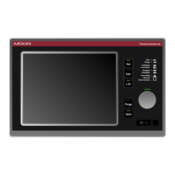
The Operative Panel is constituted by a LCD TFT 10.4 inches touch screen and by groups of buttons. The Parison Controller looks as follows: Buttons Leds panel Rotary Knob Purge Command SET key Usb Device Shift key Figure 5 MAN145-UM-D01A-EN Moog Italiana srl - Bergamo... -
Page 11: Fast Access Keys And Knob
Shift: This button used contemporarily with another button changes the operation of it. This is explained for each button in the relative pages. 2.1.2 Usb device. Usb device: Allows to save or load the recipes on an external memory. Figure 7 Moog Italiana srl - Bergamo MAN145-UM-D01A-EN... -
Page 12: Display Led Panel
End of filling: Lit at the end of the accumulator filling (only in position accumulator mode). Point out: Lit when each serial marker point is reached. End of extrusion: Lit at the end of extrusion. (both in continuous extrusion and accumulator mode) MAN145-UM-D01A-EN Moog Italiana srl - Bergamo... -
Page 13: General
Acc. Resp: Access Responsible Level on. For changing this password enter in Technical Level and enter in setup machine. Acc. Tech: Access Technical Level on. This password is fixed by Moog. The other one shows the current number page. 2.2.3... -
Page 14: Change Of Setpoints
When a field is in variation with the insertion of a new data the led near Set Key is lit and the field changes colour. It is also possible to modify all the existing fields using the relative keyboard (double click on the field): Figure 9 Figure 10 Figure 12 Figure 11 MAN145-UM-D01A-EN Moog Italiana srl - Bergamo... -
Page 15: The Parison Field
Increment; the changed point is setup as a master. by pressing SHIFT + Rotation it's possible to move the cursor upwards or downwards. Moog Italiana srl - Bergamo MAN145-UM-D01A-EN... -
Page 16: Other Possibilities
Rotate the knob to change the Smooth. The value can be from 0.5 up to 2 and it is only for Bezier interpolation Rotate the knob to setup the Serial Marker (if selected ON in Setup Machine Page) MAN145-UM-D01A-EN Moog Italiana srl - Bergamo... -
Page 17: Other Function Keys Possibilities
Language packages. PARISON CONTROLLER is supplied with a language package (application rev. IMI220145D001.X.XX). It is possible to choose among the following languages: English, Italian, German, French, Spanish, Portuguese, Danish, Russian, Turkish, Greek, Chinese and Japanese. Moog Italiana srl - Bergamo MAN145-UM-D01A-EN... -
Page 18: Elements
You can setup the maximum ON time for digital output depending on a manual command. Timer Switch The Parison Controller can manage a weekly timer switch to activate the machine heating system and it can manage a production counter. MAN145-UM-D01A-EN Moog Italiana srl - Bergamo... -
Page 19: Access
2. responsible access for responsible. Acc. Resp. For changing this password enter in Technical Level and enter in setup machine. 3. service access for installer/serviceman. Acc. Tech. This password is fixed by Moog. Access to levels 2 and 3 is password-protected. Level 2 persists at power down and power up, while level 3 does not. -
Page 20: Machine Configuration
time accumulator. In the following figures it is possible to evaluate all the configurations supported by PARISON CONTROLLER (as continuous extrusion or position accumulator). 2.5.7 Continuous Extrusion or Time Accumulator. Figure 18 MAN145-UM-D01A-EN Moog Italiana srl - Bergamo... - Page 21 3 and 4. In this way it is possible to have a completely synchronized operation of both parts. Regulators 1 and 2 will run with digital input START1 and regulators 3 and 4 will run with digital input START2. Moog Italiana srl - Bergamo MAN145-UM-D01A-EN...
- Page 22 In continuous extrusion with unique profile and with only one head it is possible to enable the alternate parison function. Every profile has the start signal (Start 1 => Profile 1, Start 2 => Profile 2), the cycle time and the correction independent. MAN145-UM-D01A-EN Moog Italiana srl - Bergamo...
- Page 23 Profile 1 and Profile 2 work with output head 1 in alternate mode. The Profile 1 starts with Start group 1 and the profile 2 starts with Start group 2. Figure 23 Figure 24 Moog Italiana srl - Bergamo MAN145-UM-D01A-EN...
-
Page 24: Position Accumulator
PARISON CONTROLLER 2.5.8 Position Accumulator. Figure 25 MAN145-UM-D01A-EN Moog Italiana srl - Bergamo... - Page 25 PARISON CONTROLLER Figure 26 Moog Italiana srl - Bergamo MAN145-UM-D01A-EN...
- Page 26 In every machine configuration type (except for alternate parison) it is possible to assign any profile to each head. If the function Free Profiles Assignment is not enabled (see Setup Machine Page) the assignment of the profiles is fixed (head 1 = profile 1; head 2 = profile 2, etc.). MAN145-UM-D01A-EN Moog Italiana srl - Bergamo...
-
Page 27: Control Update Rate
In this page it is possible to know which profile each regulator is using. 2.5.9 Control Update Rate. The close loop sampling time is normally 2 ms. In continuous extrusion with only one head the control is faster (only 1 ms sampling time). Moog Italiana srl - Bergamo MAN145-UM-D01A-EN... -
Page 28: Hardware Description
Card IMI220-6260A001 (4 Analog Output I/V 16 Bit). P/N: Ordering code (Product Code: 145; Release Level: D; hardware equipment: 001). Mfg. Date: Release date. S/N: Serial number. Reserved: Code reserved to the qualified personnel. Application Revision MAN145-UM-D01A-EN Moog Italiana srl - Bergamo... - Page 29 PWR SUPPLY: Power Supply of the display. USB1: front USB device. USB2: not to use Figure 31 KEYB: LVDS keyboard connection LCD: LVDS display connection Display Power Supply: N° Signal Not used Not used + 24V 0V24 GROUND Figure 32 Moog Italiana srl - Bergamo MAN145-UM-D01A-EN...
-
Page 30: Digital Input (Card Imi220-6100A001)
Decrease command for extruder 2 Enable timer switch Enable command from timer switch End production End of product signal Alarm Alarm signal Head in calibration Head number 1 in calibration mode Supply voltage 0V. MAN145-UM-D01A-EN Moog Italiana srl - Bergamo... -
Page 31: Analog Input (Card Imi220-6200A001)
Analog output (current) return line 1 Analog output (current) 2 Analog output (current) return line 2 Analog output (current) 3 Analog output (current) return line 3 Analog output (current) 4 Analog output (current) return line 4 Moog Italiana srl - Bergamo MAN145-UM-D01A-EN... -
Page 32: Wiring
A pin of the relevant analog input and connect pin B to the signal common as depicted in the following picture. Figure 35 MAN145-UM-D01A-EN Moog Italiana srl - Bergamo... - Page 33 PARISON CONTROLLER Wiring for Digital Input/Output and Power Supply. Moog Italiana srl - Bergamo MAN145-UM-D01A-EN...
- Page 34 PARISON CONTROLLER Wiring for continuous extrusion with Moog servo actuator cable L081-016 (Integrated Electronic Type 15Vdc). MAN145-UM-D01A-EN Moog Italiana srl - Bergamo...
- Page 35 PARISON CONTROLLER Wiring for continuous extrusion with Moog servo actuator cable L081-018 (Integrated Electronic Type 15Vdc). Moog Italiana srl - Bergamo MAN145-UM-D01A-EN...
- Page 36 PARISON CONTROLLER Wiring for continuous extrusion with Moog servo actuator in current (Integrated Electronic Type 24Vdc). MAN145-UM-D01A-EN Moog Italiana srl - Bergamo...
- Page 37 PARISON CONTROLLER Wiring for accumulator head with Moog servo actuator (Integrated Electronic Type 15Vdc). Moog Italiana srl - Bergamo MAN145-UM-D01A-EN...
- Page 38 PARISON CONTROLLER Wiring for accumulator head with Moog servo actuator (Integrated Electronic Type 24Vdc). MAN145-UM-D01A-EN Moog Italiana srl - Bergamo...
- Page 39 PARISON CONTROLLER Wiring for continuous extrusion with customer actuator. Moog Italiana srl - Bergamo MAN145-UM-D01A-EN...
- Page 40 PARISON CONTROLLER Wiring for accumulator head with customer actuator. MAN145-UM-D01A-EN Moog Italiana srl - Bergamo...
- Page 41 PARISON CONTROLLER Wiring for continuous extrusion with Moog actuator (With DCDT Type). Moog Italiana srl - Bergamo MAN145-UM-D01A-EN...
- Page 42 PARISON CONTROLLER Wiring for accumulator head with Moog actuator (With DCDT Type). MAN145-UM-D01A-EN Moog Italiana srl - Bergamo...
- Page 43 PARISON CONTROLLER Wiring for continuous extrusion Moog EMA L875-XXX. Moog Italiana srl - Bergamo MAN145-UM-D01A-EN...
-
Page 44: Terminal Measures
PARISON CONTROLLER Terminal measures. UNIT: mm Figure 36 MAN145-UM-D01A-EN Moog Italiana srl - Bergamo... - Page 45 PARISON CONTROLLER UNIT: mm Figure 37 Moog Italiana srl - Bergamo MAN145-UM-D01A-EN...
- Page 46 PARISON CONTROLLER UNIT: mm Figure 38 MAN145-UM-D01A-EN Moog Italiana srl - Bergamo...
-
Page 47: Description Of The Screen Functions
For example if you want to set 03/08/2017 (dd/mm/yy), you type 03082017 (as numeric fields) followed by Ent key. Similarly for the actual time: if you want to set 08:50:00, you type 085000 followed by Ent key. Is possible to select between European data format (dd/mm/yy) or American data format (mm/dd/yy). Moog Italiana srl - Bergamo MAN145-UM-D01A-EN... -
Page 48: Function Keys
Accumulator: Setup and display the Accumulator profile. Work extruder 1: Setup and display the extruder. Work extruder 2: Setup and display the extruder. Alarms: Display alarms from PLC and from system. Main Menu 2: Go to main menu 2. MAN145-UM-D01A-EN Moog Italiana srl - Bergamo... -
Page 49: Main Menu 2
Recipe: Recipe management. It is possible to access the recipe page only if you insert a Technician or Responsible password. All Profiles: open the all profiles page where it is possible to view all active profiles at a glance. Input / Output: Monitor status input/output digital/analogical data. Moog Italiana srl - Bergamo MAN145-UM-D01A-EN... - Page 50 PARISON CONTROLLER Setup Machine: Setup the machine configuration. It is possible to access the machine setup page only if you insert a password of Technician level. Main Menu: Go to main menu 1. MAN145-UM-D01A-EN Moog Italiana srl - Bergamo...
-
Page 51: Machine Setup
It is possible to select one of the following types of machine (in manual mode): Continuous extrusion independent profile. Continuous extrusion to unique profile. With accumulator position. With time accumulator. Moog Italiana srl - Bergamo MAN145-UM-D01A-EN... -
Page 52: General Setup Of The Machine
Suggested points Task Time 2 ms 0.6 0.8 sec 0.4 0.6 sec 0.2 0.4 sec Cycle time > 0.8 sec Suggested points Points = Cycle time (s) / Task time (s) MAN145-UM-D01A-EN Moog Italiana srl - Bergamo... -
Page 53: Machine Settings
Current Command +/- 75 mA. Current Command +/- 100 mA. 4.3.6 Languages. It is possible to select one of the following languages: English, Italian, German, French, Spanish, Portuguese, Danish, Russian, Turkish, Greek, Chinese, Japanese. Moog Italiana srl - Bergamo MAN145-UM-D01A-EN... - Page 54 PARISON CONTROLLER MAN145-UM-D01A-EN Moog Italiana srl - Bergamo...
-
Page 55: Function Keys
SET MAC2: Select Setup page 2. PREV | NEXT: Fast selection of the next or previous Setup page. The next and previous Setup Page depends on the current machine configuration. MENU 2: Select Main menu, page 2. Moog Italiana srl - Bergamo MAN145-UM-D01A-EN... -
Page 56: Machine Setup 2
The deformation of the die will be expressed in mm rather than in percentage Calibration When the deformation is expressed in mm these fields are used to set the admissible range that will be available in the work page MAN145-UM-D01A-EN Moog Italiana srl - Bergamo... -
Page 57: Function Keys
SET MAC: Select Setup page 1 PREV | NEXT: Fast selection of the next or previous Setup page. The next and previous Setup pages depend on the current machine configuration MENU 2: Select Main menu, page 2. Moog Italiana srl - Bergamo MAN145-UM-D01A-EN... -
Page 58: Work Head N / Profile N
Figure 48 The line is yellow, if working during Extrusion, green if working during Filling and red if working both in Extrusion and Filling. Synchronisms are visible only on profile 1. 4.5.2 Profile parameters. MAN145-UM-D01A-EN Moog Italiana srl - Bergamo... -
Page 59: Cycle Parameters
Marker has been set. H: Marker Height (in percentage). Value corresponding to the working gap with the opening and closing points related to the position where at the Marker has been set. Moog Italiana srl - Bergamo MAN145-UM-D01A-EN... -
Page 60: Die Gap
If enabled it sets the die gap position of the head. 4.5.5 Weight Weight: With unique profile it allows to add an additional weight on every single head. (not visible in profile). Figure 52 MAN145-UM-D01A-EN Moog Italiana srl - Bergamo... -
Page 61: Interpolation
The smooth parameter is included between 0.5 and 2.0 with step 0.1. Figure 53 Linear: Interpolation between two masters: the interpolation type visualized corresponds to the area where the cursor is placed. Figure 54 Moog Italiana srl - Bergamo MAN145-UM-D01A-EN... - Page 62 Figure 56 Parabolic 2: (parabola with tangent 0 on end point) Interpolation between two masters: the interpolation type visualized corresponds to the area where the cursor is placed. Figure 57 MAN145-UM-D01A-EN Moog Italiana srl - Bergamo...
-
Page 63: Synchronisms
In Figure 60 the PWDS is setup calibrated from -8 to +2 Figure 59 Figure 60 In the working page the following parameters are not present: Base Weight Head Tooling Die gap position Moog Italiana srl - Bergamo MAN145-UM-D01A-EN... -
Page 64: Function Keys
Bezier smoothness value. - Setup SM: rotate the knob to setup the Serial Marker. NEXT: Fast selection of the next or previous work head page. MENU 1: Go to main menu 1 page. MAN145-UM-D01A-EN Moog Italiana srl - Bergamo... -
Page 65: Head Setup
It is possible to correct the polarity of both the command and feedback with specific settings in the setup page. The procedure to check the wirings is described in the next chapter: “Check wirings”. Moog Italiana srl - Bergamo MAN145-UM-D01A-EN... -
Page 66: Check Wirings
OK and it is possible to perform the calibration in close loop. If the bar graphs are moving in opposite directions, reverse the input polarity by inverting the parameter Inv. input in the head setup page MAN145-UM-D01A-EN Moog Italiana srl - Bergamo... - Page 67 The parameter used to reverse the input polarity is only used during the close loop calibration. In work mode the polarity is derived by the values of "Vup" and "Vdown" and the polarity reversal parameter is ignored Moog Italiana srl - Bergamo MAN145-UM-D01A-EN...
-
Page 68: Calibration
With manual and automatic calibration these variables correspond to the velocity increment (%/s) to move the head in close loop. With an intelligent actuator these variables correspond to the acceleration value (mV/s) of the ramps that determine the head position. MAN145-UM-D01A-EN Moog Italiana srl - Bergamo... -
Page 69: Die Type
D-D: Die type Divergent and mobile part Die. C-D: Die type Convergent and mobile part Die. D-M: Die type Divergent and mobile part Mandrel. C-M: Die type Convergent and mobile part Mandrel. Moog Italiana srl - Bergamo MAN145-UM-D01A-EN... -
Page 70: Run Parameters
It is possible to indicate a minimum time to complete the total mandrel stroke. This time determines the maximum ramp time of the position command signal. It is possible to compensate the valves dead band and to delay movement starting. MAN145-UM-D01A-EN Moog Italiana srl - Bergamo... -
Page 71: Head Setup For Pwds
F3 to F6 are gray. Also the second Start delay time, the one used in case of alternated profiles, is not present Moog Italiana srl - Bergamo MAN145-UM-D01A-EN... -
Page 72: Function Keys
D-M: Select die type Divergent and mobile part Mandrel. C-M: Select die type Convergent and mobile part Mandrel. NEXT: Fast choose of the next or previous setup head pages . MENU 1: Select Menu 1 page. MAN145-UM-D01A-EN Moog Italiana srl - Bergamo... -
Page 73: Head Setup 2
When the error is smaller than the Minimum error no correction is made. When the error is included between the Minimum error and the Maximum error the correction is proportioned to the Maximum correction. Moog Italiana srl - Bergamo MAN145-UM-D01A-EN... -
Page 74: Correction
Photocell point: working point triggered by the photocell signal Error: difference between the control point and photocell point. Correction: calculated value of correction that will be added to the weight planned on the heads. Feedback: real actual value. Figure 70 MAN145-UM-D01A-EN Moog Italiana srl - Bergamo... -
Page 75: Function Keys
PARISON CONTROLLER 4.7.3 Function Keys. HEAD 1: Select Head page. SETUP 1: Select Setup 1 Head 1 page. NEXT: Fast selection of the next or previous setup pages . MENU 1: Select Menu 1 page. Moog Italiana srl - Bergamo MAN145-UM-D01A-EN... -
Page 76: Accumulator
OFF if accumulator position is different from end extrusion position. When the accumulator position reaches the end of filling, the digital output number 1 goes ON. MAN145-UM-D01A-EN Moog Italiana srl - Bergamo... -
Page 77: Profile Editor
Range: Displays the profile range as difference between maximum and minimum value. By changing the profile it is possible to resize the entire profile. Range: 1% to Max limit ( Weight). The max limit added to the base must be inferior or equal to 100% (base + range <= 100). Moog Italiana srl - Bergamo MAN145-UM-D01A-EN... -
Page 78: Accumulator Parameters
Volume of filling is always fixed. It's possible to change only End extruder and End filling. The analogical input referred to 100% (V. Full) has to be greater than the analogical input referred to 0% (V. Empty). MAN145-UM-D01A-EN Moog Italiana srl - Bergamo... -
Page 79: Real Position
(1…400 max). They are represented also by vertical lines on the left of the profile-edit-field. They can be activated during the extrusion, during the filling or in both movements. Figure 78 Moog Italiana srl - Bergamo MAN145-UM-D01A-EN... -
Page 80: Function Keys
CLEAR: Clear all the profile. INTERPOLATION: Change the interpolation. COPY: Copy the profile placed on Head 1 in the extrusion speed profile of the Accumulator. NEXT: Select the next or previous page. MENU 1: Select main menu 1. MAN145-UM-D01A-EN Moog Italiana srl - Bergamo... -
Page 81: Setup Accumulator
Operation: Select the operation mode of the accumulator: Work: in work mode the loop is closed, the machine works normally. No calibration is active. The calibration points are those written in the fields V. Full and V. Empty. Moog Italiana srl - Bergamo MAN145-UM-D01A-EN... -
Page 82: Run Parameters
Enable start correction: Enable the correction on the injection start position. If this correction is NO, the filling quota passed to the head is calculated always from “end of filling” point to “end of extrusion” point. MAN145-UM-D01A-EN Moog Italiana srl - Bergamo... - Page 83 Filling voltage/current: Output voltage or current to let the filling (to help the valve during the filling). During the filling it is possible to define fixed output command. Clamp voltage/current: Output voltage or current when the end of extrusion is reached. Push out delay: Delay before starting the push out. Moog Italiana srl - Bergamo MAN145-UM-D01A-EN...
-
Page 84: Regulator Parameters
Dead band negative: Value subtracted from the output already calculated by the PID controller to eliminate the dead band. Range: 0...+5000 mV or max value mA. 4.9.4 Function Keys. ACCUM.: Enter the Accumulator page. NEXT: Enter the next Setup page. MENU 1: Go to main menu 1. MAN145-UM-D01A-EN Moog Italiana srl - Bergamo... -
Page 85: Work Extruder
These setpoints can be setup: speed to be reached, rise ramp in RMP/sec., descent ramp in RPM/sec., minimum speed, maximum speed. Extruder with digital command: You can setup the maximum time for digital output. (manual command or maximum velocity control). Moog Italiana srl - Bergamo MAN145-UM-D01A-EN... -
Page 86: Extruder Command
SETUP: (yellow) Disable. (black) Enter in the setup Extruder. INC: (visible with “Digital extruder”) Velocity increment key. DEC: (visible with “Digital extruder”) Velocity decrement key. NEXT: Enter the next Setup page. MENU 1: Go to main menu 1. MAN145-UM-D01A-EN Moog Italiana srl - Bergamo... -
Page 87: Analog Extruder Setup
2). Minimum voltage: Minimum voltage in input related to 0 rpm velocity. Figure 89 Maximum voltage: Maximum voltage in input related to the maximum velocity. Velocity with V max: Corresponding velocity with Maximum voltage. Moog Italiana srl - Bergamo MAN145-UM-D01A-EN... -
Page 88: Output Calibration
(in percentage or in millisecond). The correction is applied to extruder speed (with a ramp) or to the two digital output (increment or decrement). An error greater than the window can be ignored or cause the maximum correction. MAN145-UM-D01A-EN Moog Italiana srl - Bergamo... -
Page 89: Function Keys
Error number for warning: Number of consecutive errors to visualize a warning message. 4.11.6 Function Keys. EXTR.1: Enter the Extruder page. NEXT: Enter the next or previous Setup page. MENU 1: Go to main menu 1. Moog Italiana srl - Bergamo MAN145-UM-D01A-EN... -
Page 90: Digital Extruder Setup
(in millisecond). The correction is applied to the inc\dec digital output (output 9\10 extruder 1, output 11\12 extruder An error greater than the window can be ignored or cause the maximum correction (maximum duration). MAN145-UM-D01A-EN Moog Italiana srl - Bergamo... -
Page 91: Function Keys
PARISON CONTROLLER See Analogical extruder setup. Figure 95 4.12.1 Function Keys. EXTR.1: Enter the Extruder page. NEXT: Enter the next or previous Setup page. MENU 1: Go to main menu 1. Moog Italiana srl - Bergamo MAN145-UM-D01A-EN... -
Page 92: Timer Switch
When the time indicated by the system falls within this interval the “time switch” digital output is set on. 4.13.1 Enable Timer Switch. Timer switch: Status for the timer switch. Current day: Show the current day. Figure 97 MAN145-UM-D01A-EN Moog Italiana srl - Bergamo... -
Page 93: Weekly Start And Stop Time
Time OFF: Insert the stop time. Hours and minutes for every day of the week. Figure 98 4.13.3 Function Keys MENU 2: Go to main menu 2. Moog Italiana srl - Bergamo MAN145-UM-D01A-EN... -
Page 94: Input / Output
Temperature OK: Digital Input number 10. Emergency: Digital Input number 11. Presence alarm in machine: Digital Input number 12. Figure 100 Machine in automatic: Digital Input number 13. Piece discard: Digital Input number 14. MAN145-UM-D01A-EN Moog Italiana srl - Bergamo... -
Page 95: Digital Output
Analog Output number 1. Setpoint Out 2: Analog Output number 2. Setpoint Out 3: Analog Output number 3. Setpoint Out 4: Analog Output number 4. Figure 103 4.14.5 Function Keys. MENU 2: Go to main menu 2. Moog Italiana srl - Bergamo MAN145-UM-D01A-EN... -
Page 96: Production
Number of cavity: Mould cavity. Time middle cycle: Time middle cycle. Reset: Reset production counter. Produced pieces: Real number of produced pieces. Good pieces: Good pieces. MAN145-UM-D01A-EN Moog Italiana srl - Bergamo... -
Page 97: Function Keys
Pieces discard: Discarded pieces. Pieces lacking: Lacking pieces. Time completion: Lacking time for end production. Estimated end: Estimated date and hour of end production. 4.15.2 Function Keys. MENU 2: Go to main menu 2. Moog Italiana srl - Bergamo MAN145-UM-D01A-EN... -
Page 98: Edit Profile
4.16.2 Active profiles on heads. Active profiles on heads: It is possible to see the used heads and which profile is associated to the relative head. The red line displays where is active the selected profile. Figure 107 MAN145-UM-D01A-EN Moog Italiana srl - Bergamo... -
Page 99: Function Keys
PARISON CONTROLLER 4.16.3 Function Keys. COPY: The profile currently visualized is copied in the profile showed in the field “Copy in the profiles”. MENU 2: Go to main menu 2. Moog Italiana srl - Bergamo MAN145-UM-D01A-EN... -
Page 100: Recipe
Device: Select the device where to save the recipe (Ram Disk or USB). To safely execute the commands in this page (SAVE - LOAD - DELETE - FORMAT - COPY) it is necessary to confirm the operation with the following popup. Figure 109 MAN145-UM-D01A-EN Moog Italiana srl - Bergamo... -
Page 101: Index Of The Recipes
It is possible to copy a recipe file from RAM to USB or from USB to RAM. Select a recipe file and then Press COPY. Chose the correct operation or press DEL to abort the operation. Figure 111 Moog Italiana srl - Bergamo MAN145-UM-D01A-EN... -
Page 102: Info Of The Recipes
NEXT: Scroll next the list of the files. PREVIOUS: Scroll previous the list of the files. COPY: Copy the selected recipe from RAM to the USB or vice versa. MENU 2: Go to main menu 2. MAN145-UM-D01A-EN Moog Italiana srl - Bergamo... -
Page 103: Alarms
Present events: Number of the present events. Figure 115 Previous events: it indicates that there are some previous alarms in the list Next events: it indicates that there are some following alarms in the list Moog Italiana srl - Bergamo MAN145-UM-D01A-EN... -
Page 104: List Of The Alarms
Voltage/Current with max Velocity is 0 mV. With Digital Extruder Type: the Maximum Duration Inc/Dec is 0 ms. [021] Temperature not OK. Active if the Digital Input number 10 Temperature OK is OFF. MAN145-UM-D01A-EN Moog Italiana srl - Bergamo... - Page 105 [035] Purge head 3 enable. Active if the single Purge on the Work Head 3 Page is enable. It is active even used the Fast Access Key on the front panel (All the Head). Moog Italiana srl - Bergamo MAN145-UM-D01A-EN...
- Page 106 4 is greater or equal 10000 mV and Feedback Actuator on Setup 1 Head 4 Page is OFF; the analog input 2 is greater or equal 10000 mV and Feedback Actuator on Setup 1 Head 4 Page is ON and contemporarily Show Feedback on Work Head 4 Page is ON. MAN145-UM-D01A-EN Moog Italiana srl - Bergamo...
-
Page 107: Function Keys
Active if the Digital Input number 13 Machine in automatic is OFF. [047] Unloaded battery. Active with unloaded battery. 4.18.3 Function Keys. DELETE: Delete all the alarms. (With maximum level password) MENU 1: Go to main menu 1. Moog Italiana srl - Bergamo MAN145-UM-D01A-EN... -
Page 108: Print On File
When the bitmap disappear the file is saved on USB. ATTENTION: don’t change page during this operation. To see the images on PC to use windows image browser or other program, but not Paint. MAN145-UM-D01A-EN Moog Italiana srl - Bergamo... -
Page 109: Table Of Contents
Description of the Screen Functions........................ 47 Main Menu..............................47 4.1.1 Password............................47 4.1.2 Date Change............................47 4.1.3 Function Keys............................ 48 Main Menu 2.............................. 49 4.2.1 Function Keys............................ 49 Machine Setup............................51 Moog Italiana srl - Bergamo MAN145-UM-D01A-EN... - Page 110 4.11.2 Input Calibration..........................87 4.11.3 Output Calibration..........................88 4.11.4 Velocity planned..........................88 4.11.5 Velocity control..........................88 4.11.6 Function Keys............................ 89 4.12 Digital Extruder Setup........................... 90 4.12.1 Function Keys............................ 91 MAN145-UM-D01A-EN Moog Italiana srl - Bergamo...
- Page 111 Info of the recipes..........................102 4.17.5 Function Keys..........................102 4.18 Alarms..............................103 4.18.1 Definitions alarms parameters......................103 4.18.2 List of the alarms..........................104 4.18.3 Function Keys..........................107 4.19 Print on file............................108 Moog Italiana srl - Bergamo MAN145-UM-D01A-EN...
- Page 112 PARISON CONTROLLER The Moog reserves the right to change data without prior notice. MAN145-UM-D01A-EN Moog Italiana srl - Bergamo...
- Page 113 Norway Russian Singapore South Africa Spain Sweden United Kingdom MOOG MOOG ITALIANA - Bergamo Viale 1° Maggio, n° 10 24030 Presezzo (BG) - ITALY Tel.: +39 (0) 35 43 014 11 Fax: +39 (0) 35 43 014 35 Web: www.moog.com/industrial...
Need help?
Do you have a question about the IMI220-145D001 and is the answer not in the manual?
Questions and answers